Quick CNC Process & Tooling Guide
Quick Answer: What Is CNC Router Chip Load?
CNC router chip load is the feed carried by each effective cutting edge during one spindle revolution. It is normally expressed as in/tooth or mm/tooth and is controlled by feed rate, spindle RPM, and effective cutting-edge count.
A practical starting point: Use the cutter maker’s data for the exact tool and material, calculate the matching feed/RPM relationship, then check the result on the real machine. Avoid treating one generic MDF, plywood, hardwood, or acrylic number as a setting you can copy straight into production.
CNC Router Chip Load Formula
Use consistent units: IPM with in/tooth, or mm/min with mm/tooth.
180 IPM ÷ (18,000 RPM × 2 edges) = 0.005 in/tooth.
3,600 mm/min ÷ (18,000 RPM × 2 edges) = 0.10 mm/tooth.
These are calculation examples, not recommended settings for a specific cutter or material. The number only shows the feed carried by each cutting edge. It does not tell you whether the tool, depth, workholding, chip clearing, or machine motion is right for the job.
For most standard 2-flute or 3-flute router bits, the effective cutting-edge count is normally the flute count. So a standard 2-flute bit is normally calculated with two cutting edges. If the cutter maker gives a different effective-edge count for that tool, use the maker’s value instead.
This page goes deeper into chip load itself. If your main question is the broader balance between commanded feed rate and spindle RPM across the complete routing process, use the separate CNC feed rate and spindle speed guide.
Burning, Dust, Chatter or Tool Breakage? Check This First
| What you see | First checks | Do not do first | When machine capability becomes relevant |
|---|---|---|---|
| MDF, plywood or wood: fine dust, rubbing or burning | Check tool sharpness, cutter type, chip clearing, feed/RPM relationship and whether the machine is actually reaching the programmed feed. | Do not automatically slow the feed. If RPM stays the same, slower feed reduces chip load and can make rubbing worse. | Look at machine capability only after the tool, depth, holding and chip clearing are under control and the required feed still cannot be held on the real toolpath. |
| Acrylic or plastic: melting, smeared edges or chips welding back to the cut | Check cutter geometry, flute space, tool sharpness, chip clearing and the feed/RPM relationship. Recutting hot chips can quickly spoil the edge. | Do not assume more RPM will give a cleaner finish. Extra RPM can add heat when the chip is already too small or chips cannot escape. | Machine configuration becomes relevant when a sound tool and cutting recipe still cannot get the chips out, hold the part securely or maintain the motion needed for the cut. |
| Chatter, vibration, rough edge or visible deflection | Tool stickout, collet/runout, depth, engagement, workholding and material support. | Do not assume chip load alone caused the vibration. | When stable tooling and holding still expose a stiffness, motion or process-capability limit. |
| Good straight cuts but heat or marks in corners | Toolpath geometry, acceleration/deceleration, local feed reduction, RPM and dwell behavior. | Do not judge the cut only from the programmed nominal feed. | When the production geometry repeatedly forces actual feed far below the process requirement. |
| Small parts move after breakthrough | Vacuum, spoilboard, zoning, fixture strategy and cutting force. | Do not keep changing feed/RPM while the workpiece is moving. | When the required part mix cannot be held reliably with the current table or fixture architecture. |
| Tool breakage | Entry/impact, depth, runout, holder, collision, path, workpiece movement and tool diameter. | Do not diagnose breakage from chip load alone. | When the validated process requires motion, stiffness or holding capability the current equipment cannot deliver. |
Four Rules That Prevent Most Chip-Load Mistakes
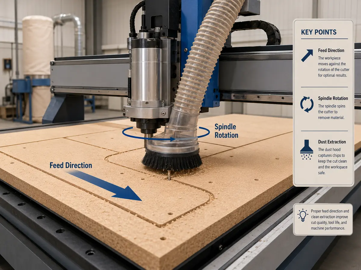
Use the exact cutter series, material and intended operation instead of copying a generic chart.
At unchanged feed and RPM, more effective cutting edges reduce feed carried by each edge.
Depth, stickout, runout, holding, extraction and local deceleration can make a mathematically correct setting unusable.
Record the tool, material, feed, RPM, depth, holding method and accepted result after validation.
How We Work Through a Chip-Load Problem
We do not look at one chip-load number and jump straight to a machine recommendation. We first work through the cut itself and find out what is really limiting the job.
- Material & drawing
- Exact operation
- Cutter & holder
- Toolmaker starting data
- Feed / RPM / chip load
- Depth & tool reach
- Holding & chip evacuation
- Output & machine configuration
This keeps the buying decision practical. There is no point moving to a larger spindle, ATC router or a different machine layout if the real problem is a worn cutter, weak holding, poor chip clearing or the wrong cutting setup.
How to Choose the Starting Chip Load
Start with the exact cutter manufacturer’s data for the exact tool series and material. The same nominal diameter can use different flute geometry, edge preparation, coatings and intended engagement, so material name alone is not enough.
| Confirm before cutting | Why it changes the usable setting |
|---|---|
| Exact cutter | Series, diameter, cutting length and effective edge count define the toolmaker’s intended operating window. |
| Material and thickness | MDF, plywood, hardwood, acrylic, plastics and composites form chips and manage heat differently. |
| Depth and engagement | Heavier engagement raises cutting force even when calculated chip load stays unchanged. |
| Tool reach and stickout | Unnecessary reach reduces stiffness and can create chatter or deflection before the target feed becomes usable. |
| Workholding | A setting is not production-ready if the part moves before the cutter reaches its intended process window. |
| Chip evacuation | Recut chips create heat and can make a reasonable feed/RPM relationship look wrong. |
How Flute Count Changes CNC Router Chip Load
More flutes are not automatically better. At the same feed and RPM, more effective cutting edges divide the feed across more edges.
At 180 IPM and 18,000 RPM:
- Two effective edges: 180 ÷ (18,000 × 2) = 0.005 in/tooth.
- Three effective edges: 180 ÷ (18,000 × 3) = 0.00333 in/tooth.
Changing from two to three effective edges without recalculating reduces the calculated load per edge by one third. Whether that is useful depends on the new tool’s geometry, material, engagement, chip evacuation and the feed the machine can actually execute.
For tool geometry and flute direction, use the CNC router bit selection guide.
Calculated Chip Load vs Usable Production Chip Load
The formula only sees feed, RPM and cutting edges. The real cut adds several things the formula cannot see.
| Constraint | What can go wrong | Production response |
|---|---|---|
| Short moves and tight corners | Actual feed can fall below the programmed value. | Inspect where heat or marks occur; do not judge only from the CAM feed number. |
| Deep cuts or heavy engagement | Cutting force rises without changing the calculated feed-per-edge value. | Validate depth and engagement separately against tooling guidance. |
| Long tool stickout | Lower stiffness can create chatter or deflection. | Use only the reach required and check the holder/collet condition. |
| Weak workholding | Part motion creates poor finish and risk even when the calculation is correct. | Fix vacuum, spoilboard, zoning, clamps or fixture strategy first. |
| Poor chip clearing | Recut chips add heat and damage the edge or tool. | Check extraction, dust shoe, pocket clearing and chip escape. |
| Dull tool or runout | One edge may carry more load while another rubs. | Inspect the cutter, shank, collet, holder and spindle interface before changing the recipe. |
A Simple Way to Tune the Cut
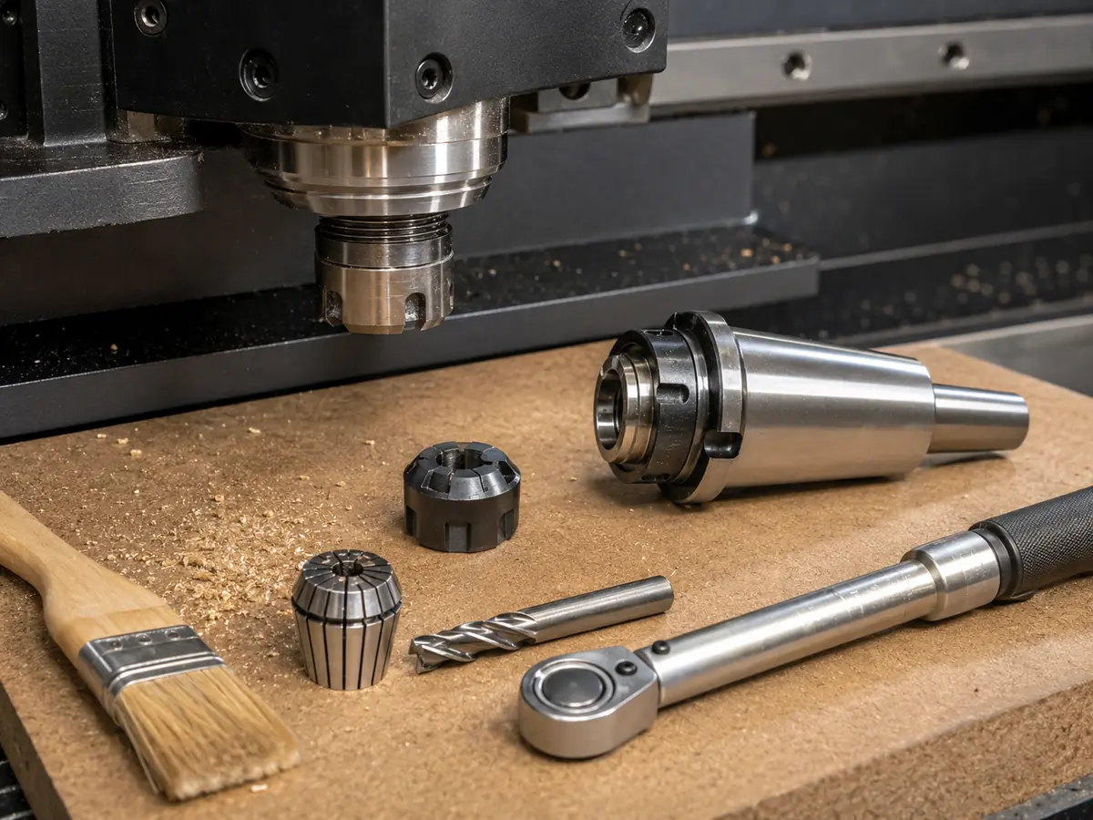
- Lock the tool: cutter series, diameter, cutting length, shank, effective-edge count and condition.
- Lock the workpiece: material/grade, thickness, surface, part size and representative operation.
- Use the toolmaker’s starting data: treat a generic online chart only as provisional when exact data is unavailable.
- Calculate feed from the selected chip load and RPM: confirm the control units before entry.
- Check process limits: depth, reach, entry, holding, extraction and whether the programmed feed is realistic for the path.
- Run one representative cut: inspect chips/dust, sound, edge quality, heat evidence, movement, vibration and tool condition.
- Change one main variable at a time: isolate feed, RPM, depth, tool, holding or evacuation.
- Save the accepted recipe: record the exact conditions that produced the accepted part.
Is the Problem in the Cut, or in the Machine?
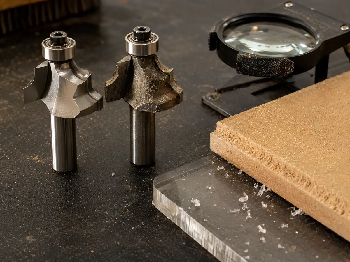
The main issue is cutter selection, wear, runout, excessive stickout, depth strategy, chip recutting, weak workholding or poor chip clearing. Correct those before treating the problem as a machine limitation.
A validated cutting process still cannot maintain the required actual feed, stiffness, holding, tool-change workflow or production throughput on the existing equipment.
If correcting the tool, holding and chip-clearing setup makes the cut stable, there is no machine problem to solve. If the same validated process remains limited on normal production geometry, then machine capability becomes part of the decision.
Not Sure Whether the Problem Is the Tool, the Setup or the Machine?
Send us one representative part, the material, cutter information and your current feed, RPM and depth. We can help narrow it down to tool/cutting setup → holding/chip clearing → machine configuration before you spend money changing the wrong thing.
Send Your Cutting Setup for ReviewWhen Chip Load Starts to Matter in Machine Selection
Chip load does not choose the CNC router for you. It becomes a machine-selection issue only after the cutter, depth, holding and chip clearing are stable and the proven process still asks for motion, stiffness, workholding or workflow capability the current equipment cannot deliver.
when the limitation is a worn or unsuitable cutter, runout, excessive reach, poor depth strategy, chip recutting, vacuum leakage or unstable fixturing.
when normal production still cannot sustain the required cutting feed, hold the part reliably, keep long-reach work stable, or avoid measurable tool-change and handling bottlenecks.
For complete machine architecture and ATC, workholding or production-flow decisions, use the CNC router for woodworking selection guide and the Quick CNC applications page.
Example
Why a Three-Flute Tool Can Run Hotter After a “Tool Upgrade”
This example is based on the calculation above. It is not presented as a Quick CNC customer case.
- Wrong action
- A shop replaces a two-edge router bit with a three-edge bit but keeps 18,000 RPM and 180 IPM because the new tool is assumed to be better.
- Consequence
- The calculated load falls from 0.005 to 0.00333 in/tooth. If that is below the new tool/material’s useful process window, rubbing, fine dust or heat can increase.
- Root cause
- The effective cutting-edge count changed without recalculating feed-per-edge or checking the new cutter’s operating data.
- Corrective action
- Reconfirm the cutter data, recalculate feed/RPM, verify depth, holding and evacuation, then test one controlled change at a time.
- What this tells you
- Do not standardize tooling by flute count alone. Confirm that the machine and process can execute the operating conditions required by the selected cutter.
What to Send Us for a Useful Cutting Review
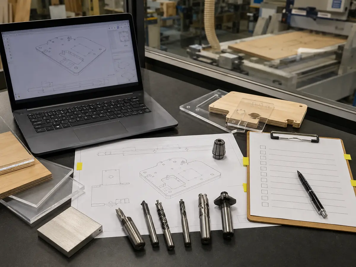
You do not need to prepare a long technical file before contacting us. These six items are enough to start a useful discussion:
Material name/grade, thickness and important surface condition.
Drawing or a clear photo of the part and the problem area.
Diameter, flute/effective-edge count and tool series if known.
Feed rate, RPM and depth per pass.
Vacuum, spoilboard, clamps, pods or fixture method.
Photo/video of burning, dust, chatter, melting, edge damage or part movement.
If available, also send: engagement/stepover, chip-extraction condition, normal production output, controller/CAM, machine working size, destination country and whether the project is troubleshooting, a new machine or a production-line upgrade.
How Quick CNC Can Help
Quick CNC manufactures CNC routers and panel-furniture production equipment for overseas B2B applications. For a chip-load or cutting-quality problem, we start with the cut itself—not by pushing a larger spindle or a higher feed-rate number.
We normally work through it in this order: material and drawing → operation → cutter and holder → feed/RPM/chip-load relationship → depth and reach → workholding and chip clearing → output target → machine and automation direction.
If the cutting process is already stable but manual tool changes, workholding, drilling, handling or cycle-time requirements remain the bottleneck, machine configuration becomes the next decision.
CNC Router Chip Load FAQ
What is chip load on a CNC router?
Chip load is the feed-per-cutting-edge value created by feed rate, spindle RPM and the number of effective cutting edges. It is normally expressed as in/tooth or mm/tooth.
How do I calculate CNC router chip load?
Use: Chip Load = Feed Rate ÷ (RPM × Effective Cutting Edges). Keep the units consistent. The result is a calculation starting point and must still be validated under the actual cutting conditions.
Is chip load the same as feed rate?
No. Feed rate is the commanded movement through the toolpath. Chip load distributes that feed across spindle revolutions and effective cutting edges, so changing RPM or flute count changes chip load even when feed stays the same.
What happens if CNC router chip load is too low?
Too-low chip load can increase rubbing and heat and may contribute to fine dust, burning, melting or faster tool wear. Check tool sharpness, chip evacuation, actual feed, RPM and effective edge count before changing the program.
What happens if CNC router chip load is too high?
Too-high chip load can raise cutting force and may contribute to chatter, deflection, rough edges or tool failure. Depth, tool reach, workholding and runout must be checked at the same time.
Does adding more flutes reduce chip load?
Yes, if feed rate and RPM remain unchanged and all listed flutes are effective cutting edges. Moving from two to three effective edges reduces the calculated feed-per-edge value by one third.
What chip load should I use for a 1/4-inch router bit?
There is no responsible universal value based only on diameter. Use the exact cutter manufacturer’s recommendation for the tool series and material, then verify depth, engagement, stickout, holding, chip evacuation and edge quality.
Why can the calculated chip load look correct but the cut still burns or chatters?
The formula cannot see a dull tool, runout, weak vacuum, excessive stickout, heavy engagement, recut chips, local deceleration, material variation or unsuitable cutter geometry. Chip load is one controlled variable inside the complete cutting system.
Technical References
- Vectric V12.5 Tool Database — calculated chip load from flute count, spindle speed and feed rate for comparison with manufacturer-recommended values.
- ShopBot Feeds and Speeds Charts — chip-load/feed/RPM formulas and process-starting guidance.
- Woodworking Network: Tooling Basics for CNC Machining — chip load in the context of tooling, holding, extraction and machine integrity.
- LMT Onsrud: The Router Way — router tooling geometry and chip-load considerations.
Send Us the Cut Problem Before You Change the Machine
Send Quick CNC the material, one representative drawing or photo, cutter information, feed/RPM/depth, workholding method and the visible cutting problem. From there, we can help separate a cutting-data problem from a holding/chip-control problem and from a real machine-configuration limit.
Submit Your CNC Routing Requirements
Frannie
Hello, I’m Frannie, a CNC machinery specialist with 15 years of experience in the woodworking CNC industry. I help furniture factories, cabinet makers, woodworking workshops, and production businesses choose CNC machines that match their production needs, factory size, budget, and efficiency goals.
My work focuses on solving real production problems, including replacing outdated equipment, improving machining efficiency, reducing labor costs, and upgrading to smarter CNC solutions. I also support customers with machine installation guidance, operation training, video support, and on-site training when needed, helping them use their machines more confidently and effectively.