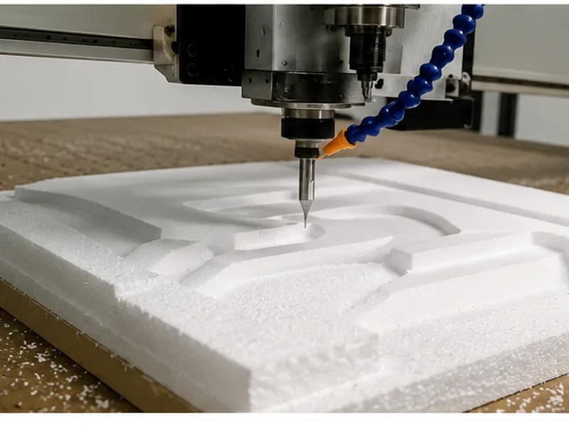
CNC Spoilboard & Workholding
For cabinet and panel-nesting production, choose the spoilboard from the workholding problem you need to solve—not simply from a standard MDF thickness. Start with the sheet material, smallest finished part, cut-through requirement, vacuum-table layout and production sequence. Then define the spoilboard material, surfacing method and replacement condition.
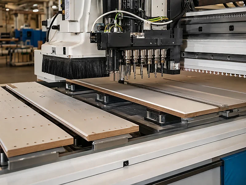
A spoilboard normally performs two important jobs on a nesting CNC router: it protects the permanent table during through-cutting and provides the working surface between the sheet and the vacuum system. But a full sheet holding securely at the beginning of a program does not prove that small separated parts will remain stable after kerfs and open areas create additional leakage.
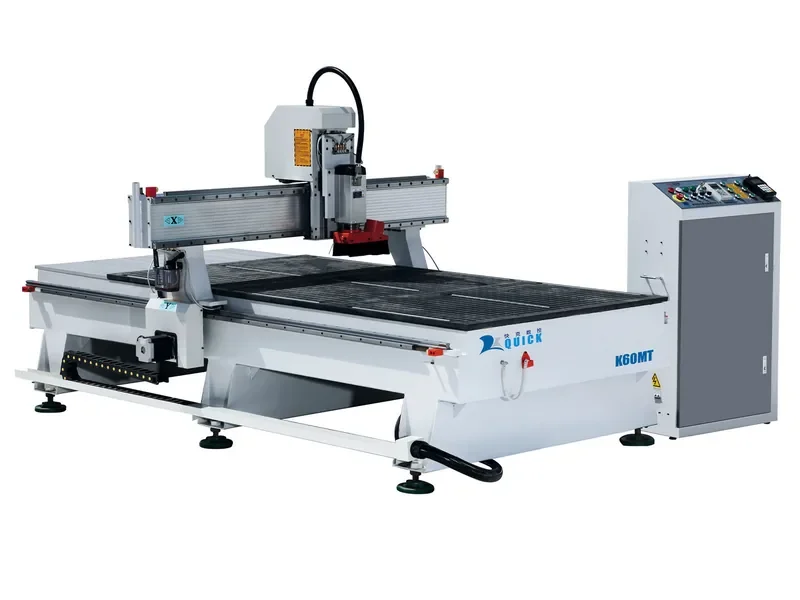
Start here: if you are buying a CNC router for nested cabinet or furniture panels, send the sheet size, smallest finished part, material, cutting sequence and production requirement together with the RFQ. These details are more useful than specifying only “vacuum table with MDF spoilboard.”
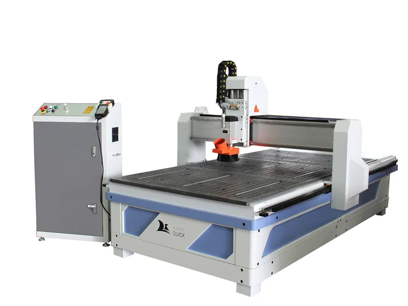
When Does Spoilboard Setup Become a Production Decision?
Cabinet, panel furniture and other sheet-processing factories using CNC nesting or repeated through-cutting.
Not only whether the machine has a spoilboard, but whether the complete table, spoilboard and vacuum arrangement can hold the actual parts throughout the machining cycle.
What Should You Decide Before Choosing the Spoilboard?
If yes, the machine needs a sacrificial layer so the cutter does not enter the permanent table.
If yes, the spoilboard is also part of the airflow path and must be considered together with zoning, leakage and part area.
Small parts are often more difficult to hold than a full sheet because they provide less effective holding area after separation.
Spoilboard thickness, material, fixtures and tooling all consume the usable machine setup height.
Start With the Sheet, Finished Part and Cutting Sequence
A spoilboard should be selected after the machining requirement is clear. For nesting production, the most important inputs are not only the full sheet dimensions but also what happens after the sheet is divided into individual parts.
| Production input | Why it changes the spoilboard or workholding decision |
|---|---|
| Sheet material | Material porosity and surface condition affect the way vacuum holding behaves. |
| Sheet dimensions | The worktable and vacuum zones need to support the normal sheet format without creating unnecessary exposed areas. |
| Smallest finished part | Small separated parts provide less effective holding area and can become unstable even when the original full sheet is secure. |
| Through-cutting | The cutter needs a sacrificial layer below the sheet, and every cut-through can create another leakage path. |
| Cutting sequence | The order in which parts are separated can change how long sufficient holding area remains. |
| Production requirement | Frequent part movement, manual intervention or rework indicates that the workholding arrangement is not suitable for the intended production process. |
Machine capability and production suitability are different. A router may be technically able to cut a small cabinet component, but if the part moves after surrounding material is removed, that process is not yet stable enough for repeat production.
What Is the Spoilboard Actually Doing?
The spoilboard is the replaceable layer above the machine’s permanent workholding structure. It should not be confused with the machine bed, vacuum plenum or permanent worktable.
| Component | Main function | What to check |
|---|---|---|
| Machine structure | Supports the machine and worktable | Do not treat this as a consumable cutting surface. |
| Vacuum table or plenum | Distributes vacuum across the work area | Check zone layout, sealing and how unused areas are controlled. |
| Spoilboard | Provides the sacrificial working surface | Check material, flatness, airflow requirement, surface condition and remaining usable thickness. |
| Workpiece | The material being machined | Check sheet size, porosity, smallest separated part and cutting sequence. |
On a flow-through vacuum table, a suitable fiberboard spoilboard can perform two jobs at once: the cutter can enter it safely during through-cuts, and air can pass through the board between the workpiece and vacuum table.
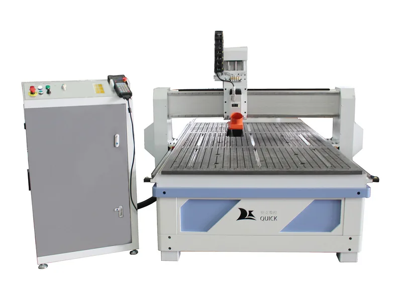
Which Workholding Setup Actually Needs a Full Spoilboard?
Do not make the spoilboard decision before choosing the workholding architecture. Different production tasks need different support and access.
| Workholding setup | What to do | When it makes sense |
|---|---|---|
| Full-sheet flow-through vacuum table | Use a compatible porous sacrificial board. | Best matched to sheet nesting and repeated panel through-cutting where most machining is performed from the top face. |
| Vacuum + T-slot combination table | Use the spoilboard according to whether the job depends on flow-through vacuum, mechanical clamping or both. | Useful when the factory processes both sheet material and jobs that require clamps or special fixtures. |
| Dedicated gasket fixture | Use a fixture-specific sacrificial layer if required. | Useful when repeated parts need controlled vacuum only in defined areas rather than across the full table. |
| Pod or raised-fixture system | Do not automatically install a full spoilboard under the workpiece. | More suitable when the cutter needs access to edges, lower surfaces or side operations. |
| Mechanical clamping | A sacrificial board can still protect the table. | Useful when vacuum is unnecessary or unsuitable for the material or part geometry. |
Do not choose a full vacuum-table setup only because it appears more automated. If the production requires frequent edge access, side machining or raised fixtures, another workholding arrangement can be more practical.
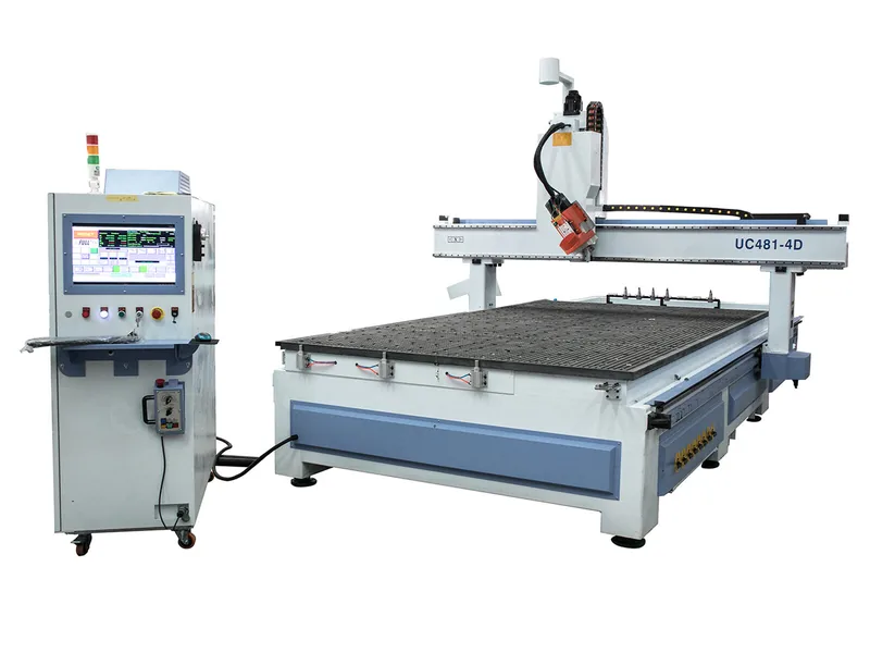
Which Spoilboard Material Should You Use, and Why Does Surfacing Matter?
For dry cabinet and panel-processing applications using flow-through vacuum, MDF or LDF is the normal starting direction because fiberboard can be machined flat and used as part of the airflow path. The final choice still has to match the table design, vacuum arrangement, sheet material and smallest finished part.
After installation, surface the board so the working face follows the machine’s actual XY cutting plane. This helps keep through-cut depth consistent across a large sheet and, on suitable flow-through fiberboard, can also expose a cleaner working face for airflow.
Check these points before production:
- airflow through the board and exposed edges;
- flatness after installation;
- leakage and sealing condition;
- how much material can still be removed during maintenance;
- whether the board is swollen, contaminated or poorly supported.
Tip: do not ask only whether “MDF spoilboard is included.” Ask what board type the workholding system is designed around and how it should be prepared, surfaced and replaced.
Why Can a Full Sheet Hold Securely While Small Parts Move?
Vacuum hold-down depends on the complete system: usable part area, material porosity, open kerfs, exposed spoilboard, vacuum zones, leakage, seals, piping, table condition, spoilboard condition and cutting force.
A full sheet starts with a large working area. As parts are cut free, that area shrinks while kerfs and uncovered spoilboard can create more leakage. The smallest separated parts can therefore become the most demanding condition in the program.
Before specifying more vacuum capacity, check:
- unused table zones and exposed areas;
- spoilboard wear, grooves and edge leakage;
- dust, seals and sheet contact;
- material porosity and smallest finished part;
- whether the cutting order releases small parts too early.
More vacuum capacity can be justified when the process genuinely needs it, but it should not be the first response to leakage or an unsuitable cutting sequence.
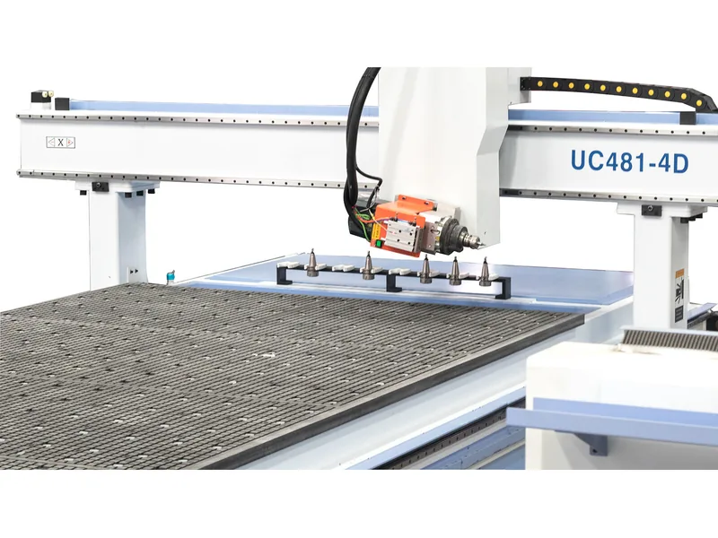
When Should You Resurface the Spoilboard, and When Should You Replace It?
| Condition | Recommended action | Reason |
|---|---|---|
| Light surface marks or minor unevenness | Clean and resurface if adequate usable thickness remains. | The board may still provide a stable reference after a light maintenance pass. |
| Depth varies across the table | Check the machine and table condition first, then resurface if the spoilboard is the cause. | Do not use surfacing to hide a mechanical alignment problem. |
| Heavy cut paths or increased leakage | Inspect sealing and exposed areas, then resurface or replace according to remaining condition. | Deep grooves can create unwanted leakage paths. |
| Swelling, crushing or contamination | Replace the board and correct the cause. | The board may no longer provide reliable support or a stable reference. |
| Insufficient remaining thickness | Replace it. | The board still needs enough material to perform its sacrificial and support functions safely. |
Do not use a fixed replacement interval. Replace or resurface according to flatness, leakage, damage, contamination and remaining usable thickness.
How Does Spoilboard Thickness Affect the Machine Configuration?
Spoilboard thickness is part of the complete vertical setup. It reduces the space available for material, fixtures, tooling and safe head clearance.
Check the full stack:
material thickness + spoilboard thickness + fixture height + tool reach + required spindle or dust-shoe clearance must fit inside the machine’s actual usable vertical envelope.
This is why advertised Z-axis travel should not be treated as the same thing as maximum usable material thickness.
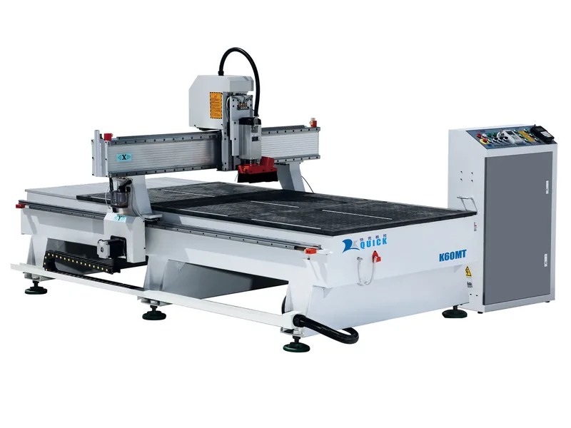
What Happens When the Full Sheet Holds but the Final Parts Do Not?
Consider a cabinet-panel nesting program where the full sheet is secure at the beginning of the cycle. After several profiles are cut completely through, the smaller components begin to shift.
Specify a larger vacuum pump immediately because the operator assumes vacuum capacity is the only problem.
The factory can invest in more vacuum capacity while leaving leakage, spoilboard condition or cutting sequence unchanged.
Finished-part area, open kerfs, exposed spoilboard, unused vacuum zones, board wear, material porosity, sealing and cutting force.
Clean and inspect the table, correct leakage, resurface or replace the spoilboard when required, control unused areas and review the part-retention and cutting sequence.
Send the smallest finished part—not only the original sheet size—when requesting a nesting CNC configuration.
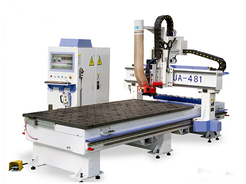
What Should You Avoid When Choosing a Spoilboard Setup?
If the material does not suit the workholding strategy, lower board cost can be offset by leakage, setup problems and unstable cutting.
The installed surface needs to match the actual machine cutting plane.
A board that is too thin, swollen or damaged should be replaced rather than repeatedly machined.
Exposed areas can become leakage paths and reduce effective holding where it is needed.
The smallest separated part can be the more demanding condition.
A larger pump does not correct damaged seals, open zones or a poorly maintained spoilboard.
What Information Should You Send With the RFQ?
Keep the workholding RFQ focused on inputs that can change the table, spoilboard or machine configuration.
Main sheet material and normal thickness range.
Full sheet dimensions and smallest finished part after through-cutting.
Show part geometry, spacing and normal cutting sequence.
Nesting, profile cutting, drilling, grooving or other required machining.
Normal output target and whether small-part movement or manual intervention must be minimized.
Vacuum flat table, combination table, clamps, fixtures or another required arrangement.
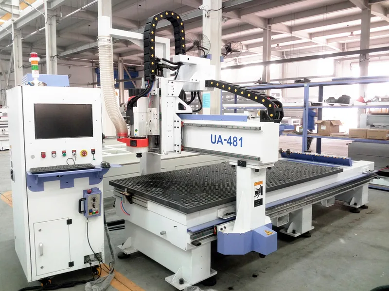
Do Not Specify the Spoilboard Without the Actual Nesting Job
Send Quick CNC the sheet material, full-sheet size, smallest finished part, CAD or representative nesting file, main operations and production requirement. We can use those inputs to review the table, vacuum and spoilboard configuration together instead of treating the spoilboard as a separate consumable.
Send My Panel Processing RequirementsHow Should You Verify the Setup?
Do not validate the system only with a full sheet. Run a representative nesting job and watch the smallest finished parts near the end of the cycle.
- Use the real or representative sheet material.
- Install and surface the spoilboard for the intended vacuum setup.
- Run a representative nesting program with normal through-cuts.
- Check through-cut consistency and the smallest separated parts.
- If holding becomes unstable, identify leakage, board condition, zoning, material, part area or cutting sequence before changing the machine configuration.
Frequently Asked Questions About CNC Spoilboards
What is a CNC spoilboard?
A CNC spoilboard is a replaceable sacrificial layer installed above the machine’s permanent workholding surface. It protects the table during through-cutting and can provide a machinable reference surface. On a flow-through vacuum table, a suitable porous spoilboard also forms part of the airflow path.
Does every CNC router need a spoilboard?
No. It is particularly useful when the cutter intentionally passes through the workpiece or when a flow-through vacuum system needs a sacrificial porous layer. Pod systems, dedicated fixtures and some mechanical-clamping processes may use another workholding or sacrificial arrangement.
What material should be used for a CNC spoilboard?
For dry cabinet and panel-processing applications with flow-through vacuum, MDF or LDF is the normal starting direction. The final choice should match the table design, vacuum arrangement, material, smallest finished part, surfacing method and shop conditions rather than one universal density or grade.
Why should a CNC spoilboard be surfaced?
Surfacing makes the installed working face follow the machine’s cutting plane and helps maintain consistent through-cut depth. On suitable flow-through fiberboard, it can also expose a cleaner working surface for airflow.
How often should a CNC spoilboard be replaced?
There is no universal replacement interval. Resurface or replace according to flatness, cut damage, leakage, swelling, contamination and remaining usable thickness.
Why do small nested parts move even when the full sheet holds well?
After parts are separated, their effective holding area becomes smaller while kerfs and exposed spoilboard can create additional leakage. The smallest finished part and cutting sequence therefore need to be considered when specifying a nesting CNC workholding system.
References
- CanCam — Spoilboard Surfacing and Vacuum Table Suction
- C.R. Onsrud — Replacing the Spoilboard on Your CNC Machine
- LMT Onsrud — The Importance of Spoilboards in the Machining Process
- Woodworking Network — Optimizing Vacuum With Spoilboard Preparation
- Quick CNC — CNC Router Parts and Their Functions
- Quick CNC — How Accurate Is a CNC Router?
Configure the Workholding System From the Smallest Part, Not Only the Full Sheet
Send Quick CNC your material, sheet dimensions, smallest finished part, a representative nesting file, required operations and production target. That is enough to review the table, vacuum and spoilboard arrangement around the real job.
Request a CNC Workholding Review
Frannie
Hello, I’m Frannie, a CNC machinery specialist with 15 years of experience in the woodworking CNC industry. I help furniture factories, cabinet makers, woodworking workshops, and production businesses choose CNC machines that match their production needs, factory size, budget, and efficiency goals.
My work focuses on solving real production problems, including replacing outdated equipment, improving machining efficiency, reducing labor costs, and upgrading to smarter CNC solutions. I also support customers with machine installation guidance, operation training, video support, and on-site training when needed, helping them use their machines more confidently and effectively.