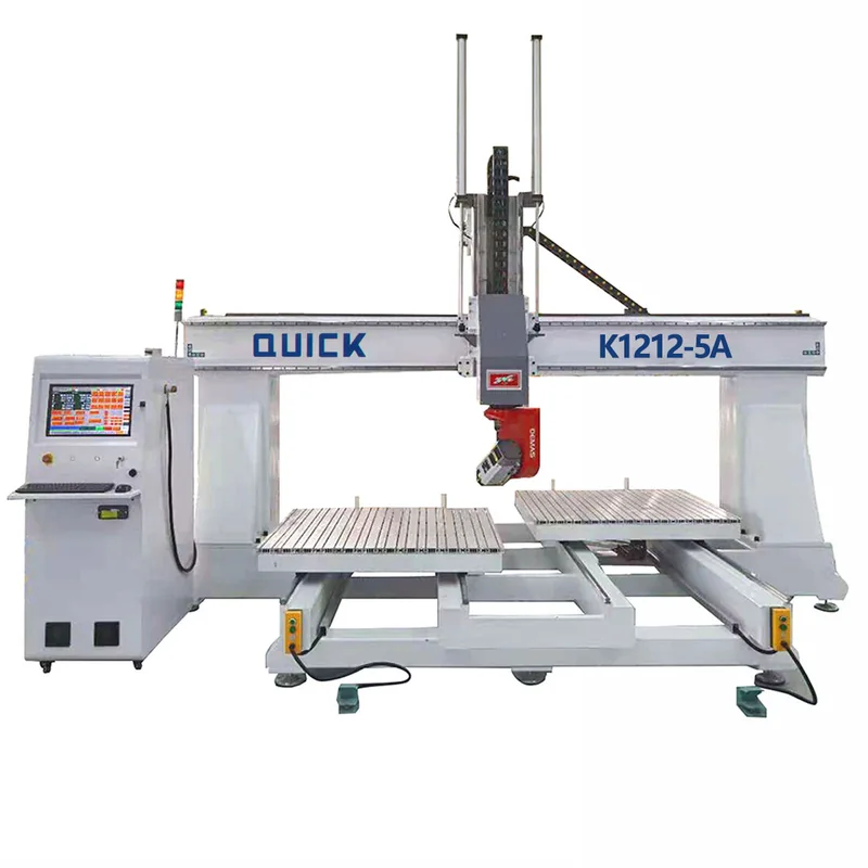
5 Axis Wood CNC Router for Molds & Complex 3D Parts — K1212-5A
When a mold, sculpture or shaped furniture component forces you to stop, flip, re-clamp and reset the datum, the production bottleneck is often tool access rather than spindle power.
The K1212-5A gives the cutter multi-angle access for five-side machining within one suitable clamping plan. Its standard setup combines a 1200 × 1100 × 800 mm working area, DEMAS five-axis head, Syntec five-axis control, 9 kW ATC spindle and 8-position automatic tool changer for molds, patterns, prototypes, sculptures and complex shaped parts.
Built for Parts a Flat-Panel Router Cannot Finish Efficiently
The K1212-5A is strongest when the part has deep geometry, curved surfaces, angled features or several machining faces that are difficult to reach from one fixed spindle direction.
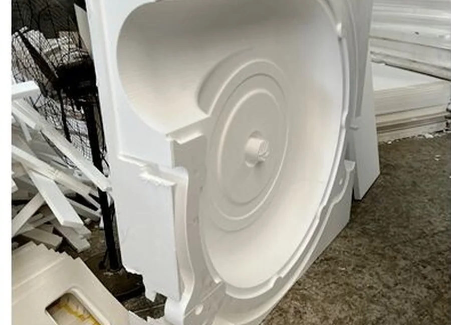
Molds & Patterns
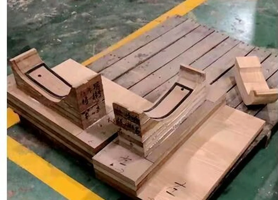
Wood molds, foam patterns, plugs and prototype tooling with deep cavities, side features and changing surface angles.
Complex Furniture Parts
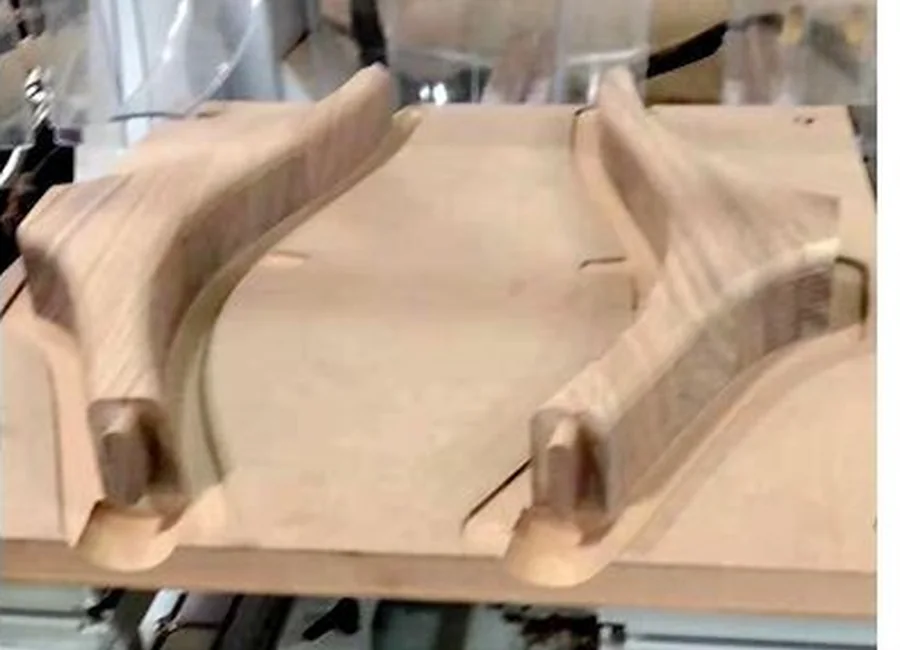
Curved solid-wood components, sculpted furniture elements, irregular architectural parts and other multi-surface work.
Sculptures & Prototypes
3D models, sculptures, custom shapes and prototype parts that need access from more than the top surface.
Selected Non-Wood Parts
Acrylic, plastics, composites and selected soft-aluminum parts when the tooling, fixture, chip control and process are suitable.
Where Five-Axis Machining Removes Production Steps
On complex parts, the cost often comes from repeated setup rather than the cutting move itself. Every time the part is turned or moved, the operator has to handle the workpiece, protect finished surfaces, re-establish the work zero and check alignment before the next operation.
| Production task | Typical 3-axis route | K1212-5A route for a suitable part |
|---|---|---|
| Top surface + angled sides | Machine the top, stop, reposition the part, reset the datum, then machine side features. | Keep more required faces within one clamping plan and orient the tool toward the accessible side features. |
| Deep cavity or curved surface | Long tools or extra setups may be needed when a vertical spindle cannot approach the surface cleanly. | Change tool orientation to improve access and maintain a more suitable cutting direction. |
| Roughing + finishing + detail work | Manual tool changes interrupt the program if the machine has no ATC. | 9 kW ATC spindle and 8 prepared tools support automatic tool changes through the programmed sequence. |
| Multiple setups | More handling, work-zero resets and fixture checks. | Fewer repositioning stages where five-side access is achievable from the selected fixture. |
The production value is simple: use five axes when they remove a real setup, reach a surface that is difficult from a fixed direction, or let one programmed process combine work that would otherwise be split across several orientations.
When the K1212-5A Makes Sense — and When It Does Not
Choose five axes when
- several faces or angles must be machined;
- deep or curved geometry limits vertical tool access;
- re-clamping is a major source of labor or alignment risk;
- the part requires complex 3D tool orientation;
- mold or prototype geometry makes a simpler process inefficient.
Choose a simpler CNC when
- the job is mainly flat panel cutting;
- cabinet parts need routine nesting and drilling;
- the geometry is 2D or 2.5D;
- one additional rotary direction solves the job;
- five-axis programming and fixturing add cost without removing a real production step.
Material boundary
The machine is positioned primarily for wood, foam, patterns and complex non-ferrous/non-metal applications. Selected soft aluminum can be considered when the tool, fixture, chip removal and cooling/lubrication strategy are appropriate. It is not positioned for steel, stainless steel, hardened metal or heavy metal removal.
K1212-5A Specifications That Matter for the Job
The specifications below define the K1212-5A setup used for five-axis process planning.
| Five-axis item | K1212-5A specification | Why it matters in production |
|---|---|---|
| XYZ working area | 1200 × 1100 × 800 mm; double-table arrangement: 1200 × 1100 × 800 mm × 2 | Part height, fixture height, tool length and angled head clearance all consume this envelope. |
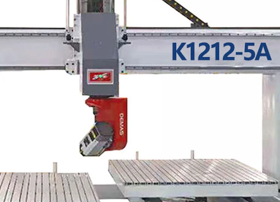
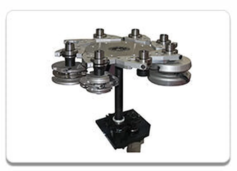
| Five-axis head | DEMAS | Provides the multi-angle tool access required for five-side and complex-surface machining. |
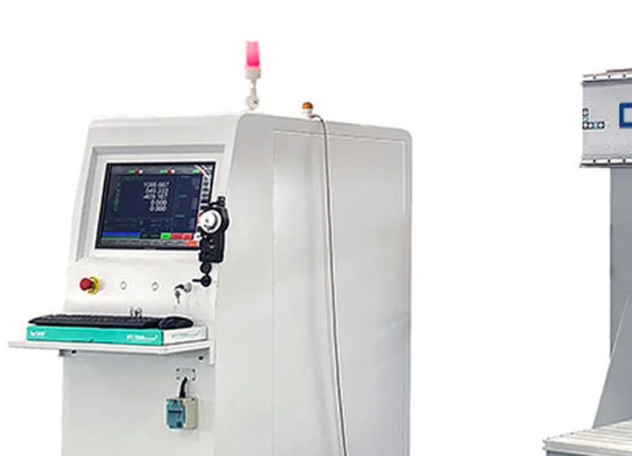
| Control | Syntec five-axis control | The Syntec control supports multi-five-axis compensation and RTCP-related functions for coordinated multi-axis motion. |
| Spindle | 9 kW ATC spindle | Supports multi-tool roughing, finishing, drilling and detail operations without manual tool changes between prepared tools. |
| Tool magazine | 8-position automatic tool changer | Eight prepared tool positions support common roughing, finishing and detail-cutting sequences; the final tool set is matched to the part and material. |
| Collet | ER32, 3.175–12.7 mm | Covers the standard tool-shank range for this setup. |
| Table | Aluminium T-slot table | Supports mechanical clamps and custom fixtures for irregular blocks and shaped parts. |
| Standard electrical supply | AC380V / 50 Hz / 3-phase | Destination voltage, phase and frequency must match the final machine electrical configuration. |
Mechanical specifications
| Item | Specification |
|---|---|
| Model | K1212-5A |
| Machine accuracy | 0.2 mm |
| Repeatability | 0.0254 mm |
| X/Y movement | Rack and pinion, gear drive / Taiwan |
| Z movement | Ball screw drive / Taiwan |
| Guide | Linear 30 square / Taiwan |
| Rack | High-precision 1.5M rack |
| Maximum speed | 0–40 m/min |
| Maximum cutting speed | 0–20 m/min; actual feed depends on tool, material and engagement |
| Inverter | Fulling |
| Drive motor | Syntec servo motor |
| Reducer | Shimpo |
| Command formats | G code, u00, mmg, plt, nc |
| Available options | Vacuum table, vacuum pump, double working table |
What the Five-Axis System Gives You in Production
DEMAS Five-Axis Head
Changes the cutting direction so the tool can approach sloped surfaces, deep areas and side features that are difficult to reach vertically.
Syntec Five-Axis Control
Coordinates multi-axis motion and supports RTCP-related and multi-five-axis compensation functions for complex toolpaths.
9 kW ATC Spindle
Supports a multi-tool process where roughing, semi-finishing, finishing, drilling or detail tools are called automatically by the program.
8-Position Tool Magazine
Keeps the required cutters ready so the machining sequence is not interrupted for every manual tool change.
800 mm Z Working Range
Provides room for taller molds, deeper 3D parts and the combined height of the workpiece, fixture and cutter.
Aluminium T-Slot Table
Gives the fixture designer flexible mechanical clamping points for irregular shapes where vacuum-only holding is not appropriate.
Choose the Table, Fixture and Tooling Around the Part
| Decision | Choose it when | What to watch |
|---|---|---|
| Single table | Your molds or complex parts are large, irregular, lower-volume or need one stable fixture zone. | Simpler fixture management and more straightforward part access. |
| Double-table arrangement | Your production benefits from separate work zones, repeat fixtures or alternating job preparation. | The actual loading sequence, safety arrangement and available head clearance must match the final configuration. |
| T-slot mechanical fixture | The part is irregular, tall, small-contact-area or sees angled cutting forces. | Clamp position must stay outside the cutter and five-axis head collision envelope. |
| Vacuum assistance | The workpiece has enough flat sealing area and the cutting direction allows stable suction. | Vacuum is not a replacement for rigid mechanical restraint on every five-axis part. |
| Tool package | The job needs roughing, finishing and detail tools in one program. | Tool diameter, length, shank size, stick-out and holder/head clearance must fit the part geometry. |
Recommended Setup Direction by Application
Instead of adding options by habit, match the fixture, tooling and machine configuration to the actual geometry and material.
| Application | Workholding direction | Tooling/process direction | Configuration priority |
|---|---|---|---|
| Wood or foam mold / pattern | T-slot table with mechanical or purpose-built fixture | Roughing tool + ball-nose/finishing tools + detail tools as needed | Tool reach, fixture clearance, Z height, CAM/post and sample finish |
| Curved furniture or architectural component | Mechanical fixture that exposes the required faces | Profile, ball-nose, drilling or detail tools according to geometry | Multi-face access, surface finish, clamp clearance and repeat fixture positioning |
| Acrylic / plastic / composite complex part | Vacuum only where sealing is reliable; mechanical support for angled or small-contact parts | Material-appropriate cutter geometry and chip/heat control | Chip evacuation, heat management, edge finish and workholding stability |
| Selected soft-aluminum part | Rigid mechanical fixture | Short, rigid carbide tooling with suitable chip removal and cooling/lubrication strategy | Alloy, cutting load, spindle/tool suitability, chip control, tolerance and finish |
| Flat cabinet panels / routine nesting | Vacuum table on a nesting or 3-axis production machine | Panel cutting, drilling and grooving tools | Do not add five-axis complexity unless the part geometry actually needs it |
From 3D Model to a Machining Plan You Can Approve
Five-axis performance is created by the machine, fixture, cutter, CAM strategy and post processor working together. Our preferred project path is:
- Part check: identify the material, overall dimensions and every surface that must be machined.
- Access and fixture plan: place the workpiece so the five-axis head and cutter can reach the required faces without clamp interference.
- Tool and CAM plan: define roughing, finishing and detail tools, then prepare the toolpath for the Syntec-controlled machine configuration.
- Simulation and collision check: verify tool reach, head movement, fixture clearance and transitions before cutting.
- Representative sample when needed: use the real material and an agreed measurement/finish standard to prove the process before production settings are locked.
For a first conversation, you do not need a complete process sheet. A 3D model, material, maximum part size and the surfaces you need to machine are enough for us to start.
How We Check the Machine Before Shipment
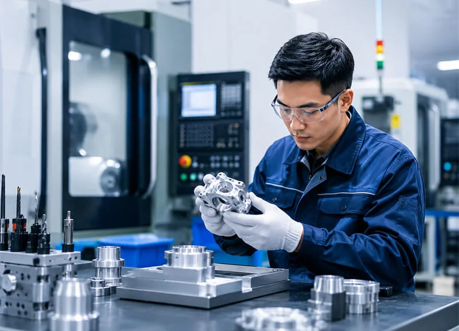
Quick CNC's factory quality-control flow covers frame inspection, component inspection, assembly check, electrical testing, running test, cutting test and packing inspection. Depending on the machine and test purpose, the factory QC system also uses spindle run-in, laser/ballbar accuracy checks, electrical safety testing, table-level checks and sample cutting.
Before shipment, the machine can be checked against the agreed order requirements. If your project needs a specific sample part, dimensional check or surface-finish target, include it in the order requirements so our engineers can plan the corresponding test method.
3 Axis, 4 Axis or 5 Axis: Choose the Simplest Machine That Solves the Part
| Part / process | Machine direction | Reason |
|---|---|---|
| Flat panels, 2D/2.5D profiling, cabinet nesting | 3-axis ATC or nesting CNC | Lower programming and fixture complexity for work that is reached from above. |
| Rotary work or parts solved by one additional rotational direction | 4-axis solution | Adds angle/rotary capability without the full complexity of five-axis machining. |
| Molds, deep surfaces, multi-face features, difficult tool-entry angles | K1212-5A five-axis CNC router | Multi-angle tool access can reduce part turning and combine more machining directions in one clamping plan. |
The number of axes is not a quality ranking. The correct investment is the machine that removes a real bottleneck in your current process.
Example Process: Deep Mold With Angled Side Features
Take a wood or foam mold with a deep top cavity, curved surfaces and several angled side features.
On a typical 3-axis route
The top geometry is machined first. To reach the side features, the part may need to be removed or rotated, clamped again, zeroed again and checked for alignment before machining continues. A second or third orientation may be required depending on the geometry.
On the K1212-5A route
The fixture is planned to expose the required faces and leave clearance for the head. The tool can then change orientation for accessible top and side features, while the ATC changes between roughing, finishing and detail tools inside the programmed process.
What still needs a second setup
Five-axis machining does not make every surface reachable from one clamp. The underside or surfaces hidden by the fixture may still require another setup. The goal is to remove unnecessary setups, not promise zero repositioning for every part.
This is the type of process comparison we can make directly from your 3D model before you choose the machine.
Production Support From Machine Build to Startup
Quick CNC manufactures CNC machinery in Jinan, China. For a five-axis project, we connect the machine structure, DEMAS head, Syntec control, spindle, tooling, workholding and CAM requirements as one production solution rather than treating them as separate component names.
Before production
Confirm the ordered working area, table arrangement, spindle/tooling, control, electrical supply and project-specific requirements.
During machine build
Follow the factory inspection and testing flow, with project-specific sample or measurement items added when they are agreed in the order.
Before shipment
We prepare the ordered machine, run the required operating and cutting checks, and complete export packing for shipment.
Start Your Five-Axis RFQ With Only 4 Inputs
You do not need to prepare a long technical questionnaire before contacting us. These four items are enough for the first machine and process discussion:
After the first process discussion, we can collect the second-step details that affect the final quotation: tolerance/finish target, production volume, preferred tools, CAM software/post processor, fixture preference, workshop voltage and destination.
MOQ, Lead Time, Packing and Logistics
Quick CNC does not require a minimum order quantity for this machine. Standard production lead time is approximately 45 days after the order and configuration are confirmed; freight transit time is separate.
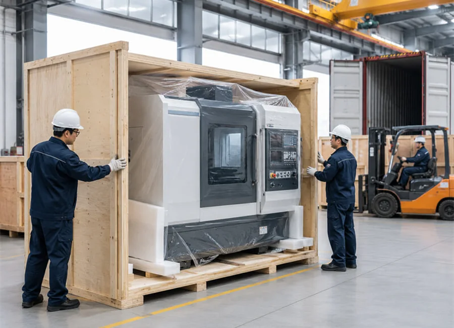
The machine is prepared for export shipment and is normally transported by container. Key moving components and machine surfaces are secured and protected before loading. Final packing dimensions and logistics depend on the ordered table arrangement, accessories and destination.
Installation, Training, Warranty and After-Sales Support
The standard company warranty period is one year; exact coverage and exclusions follow the signed agreement. Quick CNC support can include installation guidance, commissioning support, operator training, remote troubleshooting, maintenance advice and spare-parts coordination. On-site installation or training can also be arranged when included in the project scope.
For teams moving from 3-axis to 5-axis machining, our support can also cover coordinate setup, tool-length management, CAM/post preparation, fixture planning, collision checking and the operating sequence.
Frequently Asked Questions
Can the K1212-5A machine five sides of a part in one clamping plan?
For suitable geometry and fixturing, the machine is designed for five-side machining so more required faces can be reached without repeatedly turning the workpiece. The underside or any surface hidden by the fixture may still require another setup.
What does the Syntec five-axis control add?
The Syntec five-axis control supports coordinated five-axis motion, multi-five-axis compensation and RTCP-related functions. Reliable machining also depends on a matching CAM post processor, correct tool data and the final machine configuration.
What A/C head travel and usable angled envelope will I receive?
These values directly affect reach and collision clearance, so they should be stated for the ordered head/control configuration in the technical sheet or agreement. We do not substitute rotary-angle data from a different five-axis model.
Why are machine accuracy and repeatability listed as different numbers?
The published model sheet lists 0.2 mm machine accuracy and 0.0254 mm repeatability. They are different metrics, not duplicate measurements. If part tolerance is a purchase requirement, state the required sample, measurement points and tolerance target for the ordered machine.
Is this machine suitable for cabinet production?
Not for ordinary panel nesting, flat-sheet cutting and routine drilling. It becomes relevant only when cabinet, door or furniture components have complex 3D surfaces, several machining faces or difficult tool-access angles.
Can it machine wood molds and foam patterns?
Yes. Mold, pattern, prototype and complex 3D work are core applications for this machine family. Fixture design, tool selection and CAM strategy should match the real geometry and material.
Can it machine acrylic, plastics, composites or soft aluminum?
Acrylic, plastics and composites can be processed when the cutter, heat/chip control and workholding are suitable. Selected soft-aluminum work can also be considered with a rigid fixture, appropriate tooling, chip removal and cooling/lubrication plan. The machine is not positioned for steel or heavy metal removal.
Does it include automatic tool changing?
The K1212-5A setup includes a 9 kW ATC spindle and an eight-position automatic tool changer.
What do I need to send for a first quotation?
Start with a 3D model or drawing, material, maximum part size and the surfaces you need to machine. Tolerance, production volume, CAM, voltage and other details can be collected after the first process discussion.
What are the lead time and warranty?
Standard production lead time is approximately 45 days after order and configuration confirmation. The standard company warranty period is one year, with the final scope controlled by the signed agreement.
Send the Part That Is Difficult on Your Current CNC
If your current process involves repeated part turning, difficult side access, deep 3D surfaces or several separate machining orientations, send us that actual part—not a generic machine request.
We will use the geometry to match the K1212-5A working envelope, head access, fixture direction, tool list and CAM/post requirements. The result should be a machine configuration tied to the part you need to produce, not an option list with features you may never use.
Related CNC Router Options and Selection Guides
If your parts do not need multi-angle five-side access, compare this machine with a three-axis ATC router, four-axis solution or nesting CNC before adding five-axis programming and fixture complexity. Use the CNC Router category and the 3, 4 and 5 axis selection guide to narrow the machine family.