Before You Choose the Machine
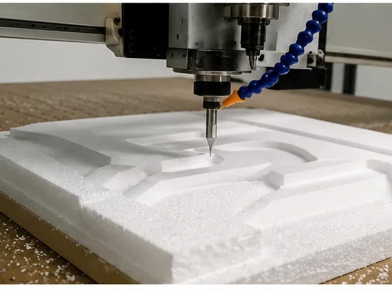
CAD and CAM are not alternatives in a CNC router workflow. CAD defines the part geometry; CAM decides how that geometry will be machined and creates toolpaths. A post processor then converts those toolpaths into machine-ready code for the selected controller, which executes the program on the router.
Don’t choose the router first and worry about the software later. Run one real job from the design file to the machine-ready program before you lock in the machine setup.
What You Need to Figure Out Before Buying
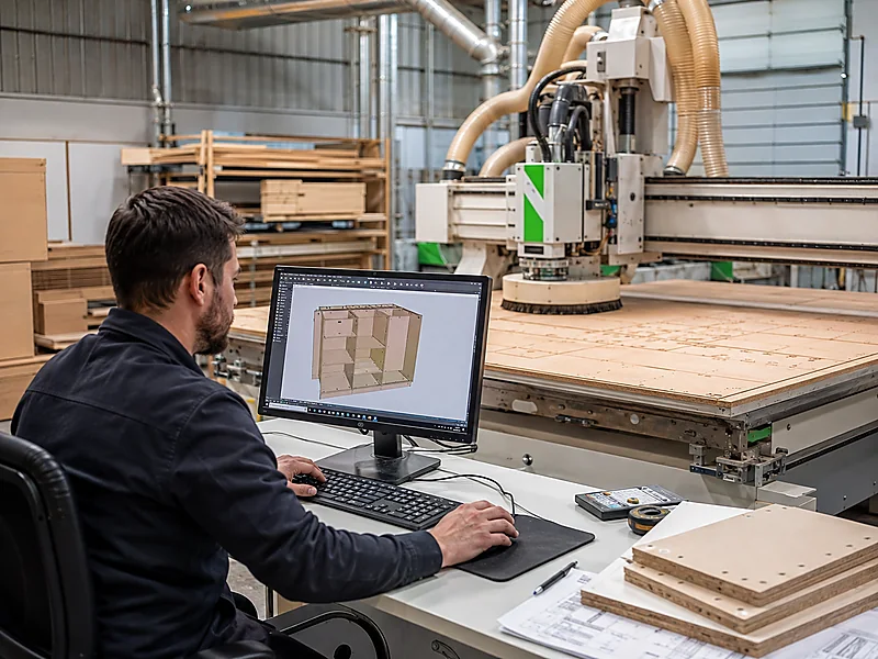
Before you order a CNC router, you need to know one simple thing: can your current files and software actually run the jobs you want on the new machine? We’ll walk through CAD, CAM, the post processor, and the controller so you can spot problems before the machine arrives.
Key Takeaways
It creates or edits 2D drawings, 3D models, dimensions, and geometry.
It assigns tools, operations, toolpaths, cutting parameters, and machining order.
A valid drawing file is not enough; machine code must match the controller and machine configuration.
Flat panels, ATC work, nesting, drilling, rotary work, and 5-axis machining do not require the same CAM functions.
CAD vs CAM: What Does Each One Actually Do?
The practical difference is simple: CAD answers “what should the part be?” while CAM answers “how should the router make it?” A CAD model can be geometrically correct and still be impossible or inefficient to machine with the selected cutter, workholding method, axis arrangement, or tool access.
| Decision Area | CAD | CAM | Why It Matters to the CNC Router |
|---|---|---|---|
| Main purpose | Create or edit geometry | Create machining operations and toolpaths | The router needs executable motion, not only a drawing |
| Typical work | 2D profiles, dimensions, 3D models, assemblies | Tool selection, cut order, pocketing, drilling, profiling, roughing, finishing | The process must match the machine and the workpiece |
| Main output | Design/model data | Toolpath data, then NC code through a post processor | The controller must receive code in the format and logic it supports |
| Machine awareness | Often limited to design constraints | Must account for tools, axes, work zero, operations, and machine/controller output | More complex machines need more complete CAM and post support |
How Does a Job Get From Your Drawing to the CNC Router?
For industrial CNC router production, treat the digital chain as four separate responsibilities even when one software package combines several of them.
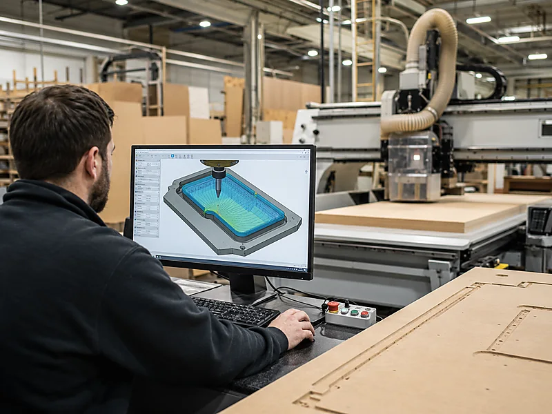
- CAD: create or receive the part geometry, cabinet design, door profile, sign vector, mold surface, or other production model.
- CAM: define machining operations, choose tools, set cutting strategy, order the operations, and calculate toolpaths.
- Post processor: convert the CAM toolpath data into NC code that matches the controller and the machine configuration.
- CNC controller: load and execute the approved program while coordinating axes, spindle, tool changes, offsets, and supported auxiliary functions.
Even when one program combines several steps, the same responsibilities still exist. For a new router, check whether the complete chain supports the exact operations and hardware you plan to use.
Do You Really Need Both CAD and CAM?
Most factories need both functions, but not necessarily two separate software products. If you already receive finished geometry from customers or cabinet-design software, the CAD work may be done; you still need CAM or another manufacturing step to turn that data into usable machining operations.
A more powerful CAD package does not replace CAM. The router still needs tools, toolpaths, machining order, work zero, drilling logic, tool changes, and the correct post output.
| Your Workflow | Recommended Software Direction | Main Check Before Machine Selection |
|---|---|---|
| Simple signs, profiles, pockets, 2D/2.5D parts | Integrated CAD/CAM can keep the workflow compact | Toolpath types and post support for the selected controller |
| Furniture or cabinet design from specialized software | Keep the design system if it already controls product data; connect it to suitable CAM/nesting output | Part naming, drilling/groove data, nesting flow, labels if used, and machine code output |
| Custom 3D furniture parts or molds | Use CAD that handles the required surfaces/solids and CAM that supports the needed 3D strategies | Tool access, finishing strategies, machine envelope, and post support |
| Rotary, indexed, or simultaneous multi-axis work | Use CAM that explicitly supports the required axis strategy | Machine kinematics, axis conventions, controller capability, and validated post |
One CAD/CAM Package or Separate Software?
Use integrated CAD/CAM when the same team changes both the design and the machining. It cuts down on repeated file transfers and keeps model changes closer to the toolpaths.
Keep specialized software when it already runs an important part of production. In cabinet factories, product data, part lists, drilling information, nesting, labels, and order data may already come from the design system. The job is to make that output work with the new router and downstream equipment—not replace a workflow that is already doing its job.
Already Have CAD/CAM? Don’t Replace It Without a Reason
If your team already has a stable design and programming workflow, the first question is not “Which new software should we buy?” It is “Can the new CNC router work with what we already use?” Replacing proven software can add retraining, file-conversion work, new post-processor risk, and production disruption without improving the finished part.
| Current Situation | Better Direction | What to Verify |
|---|---|---|
| Your current CAD/CAM already programs the required operations | Keep it where practical | Confirm the correct post processor, controller output, tool logic, and file-transfer workflow for the new router |
| Your software designs the parts but cannot program new machine functions | Add or upgrade CAM/post capability | ATC calls, drill-bank output, nesting, rotary or multi-axis strategies |
| Your current workflow forces repeated manual data entry | Review the complete data flow | Part IDs, drilling data, nesting, labels, order data, and downstream equipment |
| Your existing software is already the factory standard | Configure the machine around the proven workflow when possible | Use a representative production file to confirm compatibility before the machine is finalized |
Match the Production Job to the CAM Functions You Actually Need
Do not choose software by the machine name alone. Start with the operations you need to program, then confirm that the CAM system and post processor support those functions on the selected controller.
| Production Need | Machine Type That Fits | CAM / Post Priority |
|---|---|---|
| Profiles, pockets, grooves and ordinary drilling | 3-axis CNC router | Reliable 2D/2.5D toolpaths, required 3D strategies and the correct post for the controller |
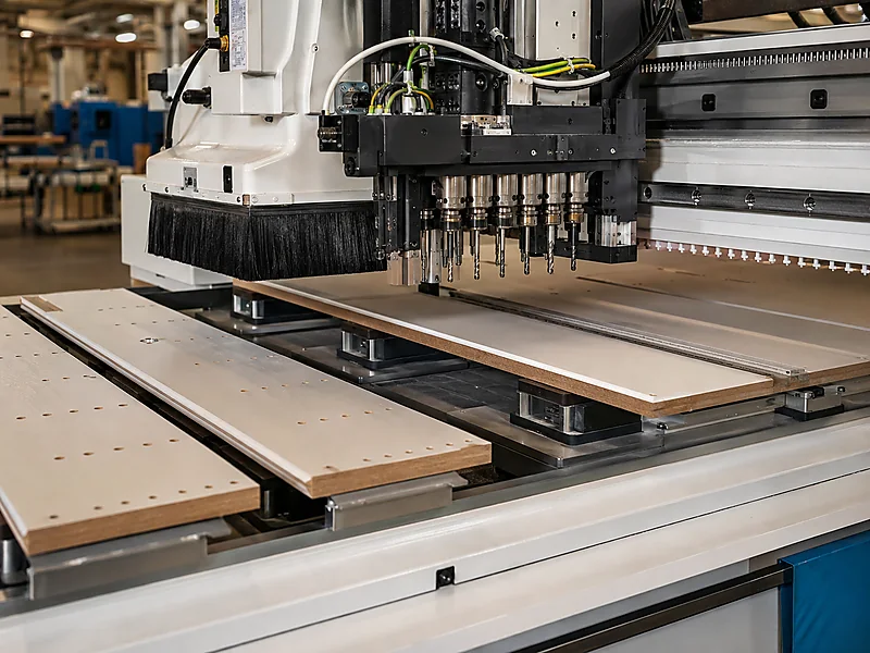
| Several cutters in one job | ATC CNC router | Tool numbering, automatic tool-change commands, offsets and multi-tool post output |
| Cabinet parts nested from full sheets | Nesting CNC machine | Nesting, part data, cutting, grooving, drilling and production-data flow |
| Rotary or multi-axis machining | 4-axis or 5-axis solution | Axis strategy, machine kinematics, controller capability and a validated post processor |
If you are still deciding between axis counts, review Quick CNC’s 3-, 4-, and 5-axis CNC router guide. This page keeps the focus on software compatibility rather than repeating the full machine-selection process.
Will Your CAD/CAM Setup Work With the New CNC Router?
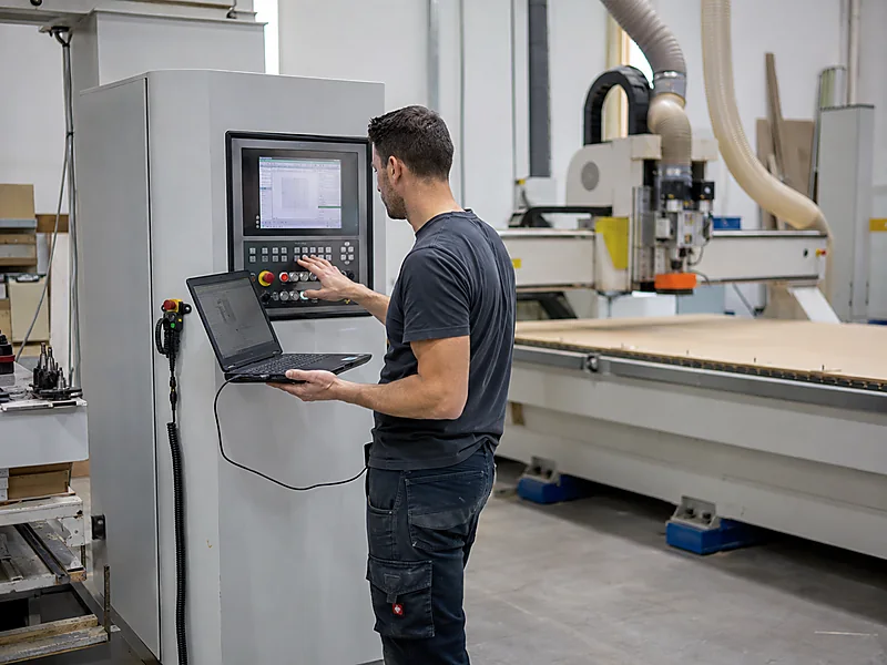
Don’t stop at “Which CAD or CAM do you use?” Take one real part and follow it all the way from the design file to the machine program. Two shops can use the same software and still need very different machine setups.
| Check | What to Confirm | Why It Changes the Purchase |
|---|---|---|
| Input geometry | Your real 2D/3D file types and how revisions are handled | Avoids repeated redraw or conversion work |
| Required operations | Profiles, pockets, drilling, grooves, engraving, reliefs, nesting, rotary or multi-axis work | Determines CAM function depth and machine type |
| Tool management | Manual tools, ATC tool numbers, drill-bank tools, offsets | Prevents tool-call and setup mismatches |
| Post processor | Post matched to the selected controller and axis configuration | Determines whether toolpaths become usable NC code |
| Controller workflow | Program transfer, file handling, offsets, tool tables, supported commands | Affects operator ramp-up and daily execution |
| Production data | Nesting data, part IDs, labels, order information, downstream links where required | Important for cabinet and panel-furniture production |
| Operator capability | Who designs, who programs, who proves out, who runs production | Changes training needs and software complexity |
One thing to keep in mind: CAM software does not all work the same way. Before you settle on the machine, make sure your CAM and post processor can handle the functions you plan to use. The links at the end of this page are general software references, not a promise that every package works with every Quick CNC configuration.
What Can Go Wrong
ATC Is Added, but the Software Was Never Checked
A furniture factory moves from manual tool changes to an ATC router. The CAD files are fine, but the current CAM/post setup has never generated the automatic tool-change commands needed by the new controller.
- What happens
- Operators start editing programs by hand, tool numbers do not match, and the ATC cannot be used the way the factory expected.
- Why it happens
- The CAM, post processor, controller, and physical tool positions were never checked together before the machine setup was finalized.
- How to avoid it
- Run one real multi-tool job and check tool numbers, post output, controller behavior, and the operator steps before shipment and training.
- What this tells you
- Software compatibility is part of the machine setup, not something to leave until after installation.
CAD/CAM Mistakes We See All the Time
Mistake: “My CAD file opens, so it will run.”
Consequence: geometry imports correctly but the machine still lacks valid toolpaths and controller-specific code.
Correction: verify the entire CAD → CAM → post → controller chain.
Mistake: choosing CAM by brand popularity
Consequence: the software may not support the nesting, drill-bank, aggregate, rotary, or multi-axis functions your production requires.
Correction: build the requirement list from real parts and operations first.
Mistake: ignoring existing factory software
Consequence: operators re-enter part data, recreate toolpaths, or lose order/nesting information.
Correction: map the current digital workflow before replacing or adding software.
Mistake: validating only a simple demo file
Consequence: advanced functions fail later on real orders.
Correction: use representative drawings that include the hardest operations and tool sequence you expect to run.
What Should You Check Before You Lock In the Machine Setup?
Once the machine type is clear, confirm only the details that can still change the software and hardware setup: required operations, tool count, drilling needs, axis access, controller, post processor, operator workflow, and production target.
For cabinet, nesting, or multi-axis work, make sure the software chain can carry the required part data and machine functions before you add more hardware. Extra machine capability only helps when the CAM, post processor, controller, and operator workflow can use it reliably.
Five Things Are Enough for the First Compatibility Check
Send one real job you actually need to make. A representative file, your current software and the machining steps tell us much more than simply saying you need “CAD/CAM support.”
Send a typical 2D drawing, 3D model, cabinet file or other real production file.
Tell us the CAD, CAM, nesting or cabinet-design software you already use, plus the current post processor if available.
List cutting, pocketing, grooving, drilling, engraving, nesting, ATC, rotary or multi-axis work that matters to the job.
Tell us the typical tool count and whether you need ATC, drill-bank, rotary, aggregate or other special functions.
Give us your typical batch size, shift output or the bottleneck you want the new machine to remove.
Want Us to Check Your Current Software Setup?
Send one representative part file, your current CAD/CAM software and version, the operations you need, and your typical tool count. We can check the main compatibility points before you finalize the machine.
Send a Part File for Compatibility ReviewQuestions We Often Get About CAD, CAM, and CNC Routers
Can a CNC router run directly from a CAD file?
Not in a normal production workflow. CAD provides geometry; CAM creates the machining operations and toolpaths, and a post processor outputs code for the selected machine and controller. Some integrated systems hide several steps, but the manufacturing logic still has to be created.
Can one software package handle both CAD and CAM?
Yes. Integrated CAD/CAM can be efficient when the same team designs and programs parts. The important check is whether the package supports your required router operations, post processor, controller, nesting or drilling functions, and any rotary or multi-axis work.
What is a CNC post processor?
A post processor converts CAM toolpath data into NC code formatted for a particular controller and machine configuration. It is a critical compatibility layer because machines can require different commands, tool-change logic, axis conventions, and auxiliary functions.
Is nesting software the same as CAM?
They can overlap, but they are not automatically the same. Nesting software focuses on arranging parts efficiently on sheets and may also generate machining data. Cabinet-production systems can add part, drilling, labeling, or order information. Confirm what the system outputs and whether that output matches the selected CNC machine.
Does an ATC CNC router need special CAM setup?
Yes. The program must call tools in a way that matches the post processor, controller tool table, and physical tool positions. If those three are inconsistent, the machine cannot use the automatic tool-change workflow reliably.
What changes in CAM for 4-axis or 5-axis CNC routing?
The CAM system must support the required rotary or multi-axis machining strategy, and the post processor and controller must match the actual axis configuration. More machine axes are useful only when the software and operator workflow can program and execute the required motion.
What CAD/CAM information should I send before requesting a CNC router quotation?
For the first compatibility check, send one representative part or production file, your current CAD/CAM software and version, the machining operations you need, your typical tool count or special machine functions, and your production target. If you already have a post processor, include it too. Workpiece range, utilities, floor space and destination can be confirmed after the software chain and machine type are clear.
Software References
- Autodesk — CAD/CAM software overview: integrated design-to-manufacturing workflow and CAM capability context.
- Autodesk — CNC machining software: CAM toolpaths, NC programs, post processors, controller types, and axis configuration.
- Mastercam — CNC Router software: router-oriented nesting, drilling, aggregate, and multi-axis programming functions.
- Vectric VCarve Pro documentation: machine selection, post-processor association, and saving toolpaths for CNC machines.
Send One Real Job and Your Current Software
Send one representative part or production file, your current CAD/CAM software and version, the machining operations you need, your typical tool count or special machine functions, and your production target. That is enough for us to start checking software compatibility and machine fit.
Send a Part File for Compatibility Review
Frannie
Hello, I’m Frannie, a CNC machinery specialist with 15 years of experience in the woodworking CNC industry. I help furniture factories, cabinet makers, woodworking workshops, and production businesses choose CNC machines that match their production needs, factory size, budget, and efficiency goals.
My work focuses on solving real production problems, including replacing outdated equipment, improving machining efficiency, reducing labor costs, and upgrading to smarter CNC solutions. I also support customers with machine installation guidance, operation training, video support, and on-site training when needed, helping them use their machines more confidently and effectively.