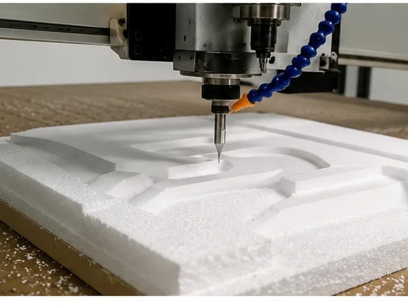
Quick Answer
A CNC router is a good production choice for solid wood when the machine is chosen around the actual part—not just table size or spindle power.
For mainly flat furniture parts, start with a 3-axis CNC router. Add ATC when the same part regularly needs several cutters. Look at rotary or 5-axis only when the geometry really needs machining around the part or from several directions. With solid wood, the bigger problems are normally blank movement, grain tear-out, burning, weak holding near the end of the cut and variation from one blank to the next.
Start With These Four Questions
Before looking at machine models, get four things clear: what the part looks like, how many sides need machining, how you will hold it, and how many tools the normal program uses.
Three Things That Make the Biggest Difference
- Do not rely on vacuum for every solid-wood part. Wide, flat blanks may hold well on a vacuum table, but narrow, warped or irregular parts often need stops, clamps, fixtures or pods as well.
- Roughing and finishing are different jobs. Remove the bulk of the material first, leave a controlled amount for finishing, then choose the final cutting direction around the edge and grain you need to keep clean.
- Test the kind of part you actually make. An easy demo blank will not tell you much about a long chair rail, a warped hardwood blank or a part that becomes difficult to hold near the final profile.
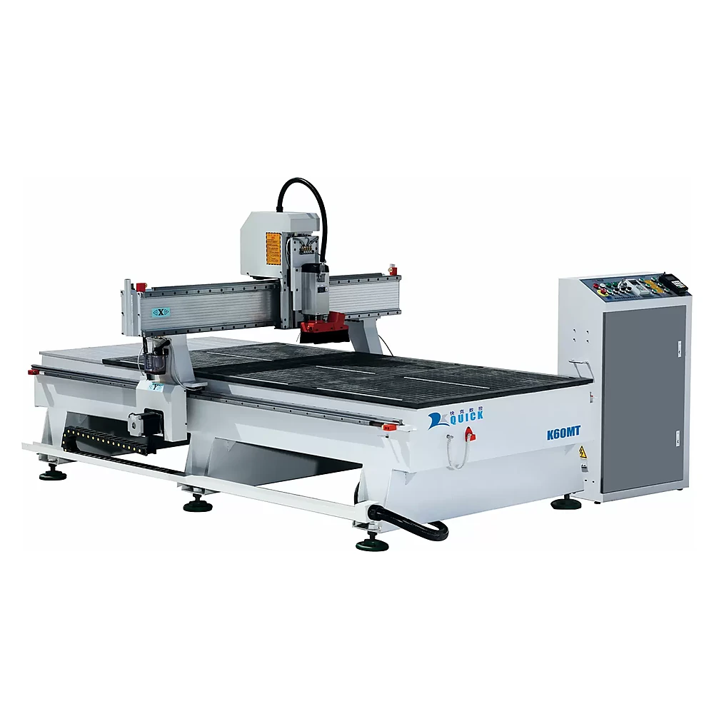
When a CNC Router Is a Good Fit—and When You Need More Planning
- Furniture rails, panels, fronts, shelves and shaped components
- Door faces, pockets, hinge and lock features
- Stair parts, balusters and columns
- Relief carving, profiling, drilling and joinery work
- Repeat parts that can use saved fixtures and programs
- Twisted or natural-edge blanks
- Small parts with very little holding area
- Deep pockets with long cutter reach
- Parts with undercuts or difficult side access
- Jobs where blank moisture and size keep changing
On This Page
- Why solid wood needs a different plan
- Choose the machine
- What matters in the machine setup
- How to hold the part
- Choose the cutter
- Cut in the right order
- Fix common problems
- A common machine-selection mistake
- Why the real production part matters
- Which machine fits your parts?
- Common solid-wood CNC questions
Solid Wood Does Not Behave Like MDF
MDF and other sheet materials are relatively consistent. Solid wood is not. Grain direction, density, knots, resin, moisture and drying history can all change the cut. A program that leaves one blank clean can tear the next one if the grain reverses or the part moves after material is removed.
Moisture can change the finished size
Solid wood can shrink or swell as moisture changes, and it does not move the same amount in every grain direction. If the part has to fit into a door opening, line up with another component or keep a narrow reveal, do not judge the result only from the dimension taken immediately after machining.
USDA wood-property references explain this dimensional movement. In production, the practical point is simple: keep the incoming wood condition under control and measure parts under a consistent condition.
Grain decides where tear-out shows up
Straight grain, end grain, reversing grain and the area around knots can all cut differently. Mark the visible edge first, then decide cutter direction, lead-in position and finishing allowance around that edge.
The blank needs a real reference surface
The CNC machine can repeat coordinates very accurately, but it cannot fix a blank that rocks or moves on the fixture. Decide which face locates the part, where the stops are, and which reference face (datum) remains usable after profiling.
Choose the Machine From the Part, Not the Axis Count
Use the simplest machine that can reach all the features without creating unnecessary repositioning. More axes give you more access, but they also add programming, fixture and collision-control work.
| Machine | Where it fits | Why it makes sense | What to check |
|---|---|---|---|
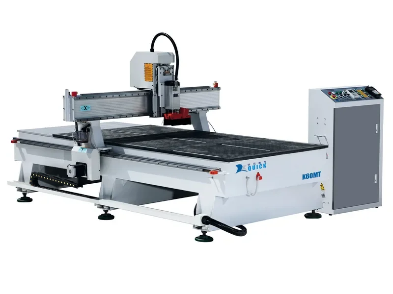
| 3-axis flatbed CNC router | Flat faces, pockets, profiles, drilling and reliefs reached from the top | Simple process and flexible fixturing | Side and back features may need a second setup |
| 3-axis ATC CNC router | Repeat parts using several cutters | Removes repeated manual tool changes | ATC will not fix poor holding or inaccessible faces |
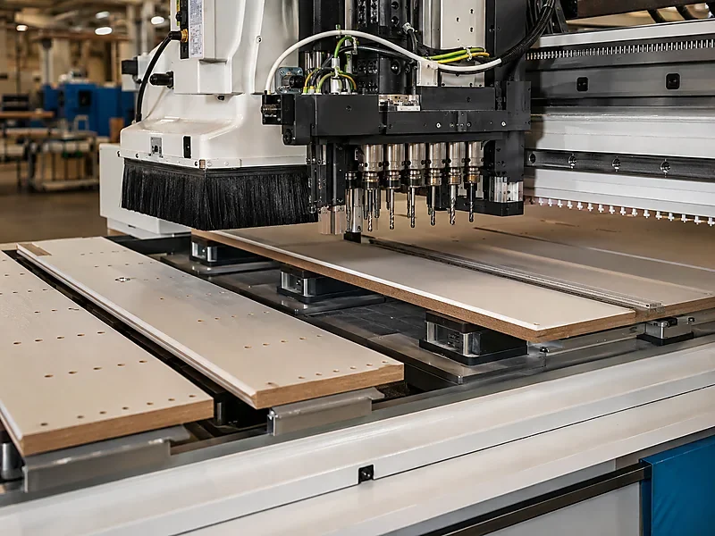
| PTP / pod-and-rail setup | Doors and individual furniture parts that need flexible support and more room around selected edges or machining areas | Pods and clamps can support individual parts while leaving more usable cutter access around selected areas | Pod and clamp positions, cutter access and collision zones all need to match the real part family |
| Rotary-axis setup | Balusters, columns, legs and parts built around a centerline | Lets the part rotate without repeated manual indexing | It does not replace full multi-face machining |
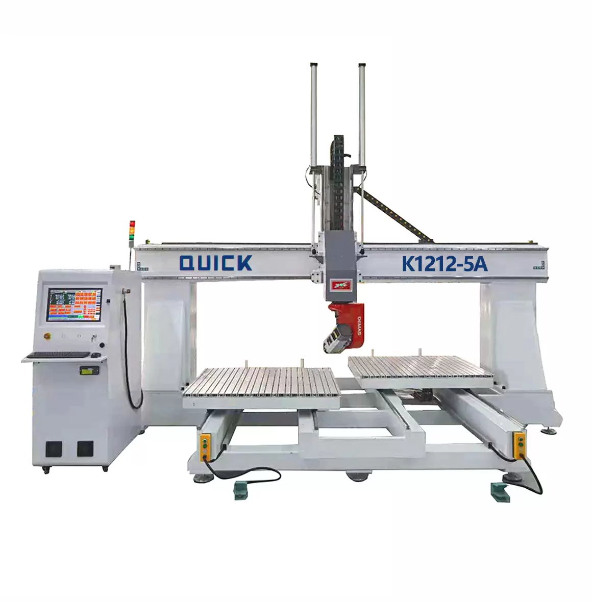
| 5-axis CNC router | Compound surfaces and parts that genuinely need tool access from several directions | Reduces some repositioning and gives more tool angles | Only worth it when the part family really needs that access |
For a broader comparison, see 3-axis, 4-axis and 5-axis CNC routers .
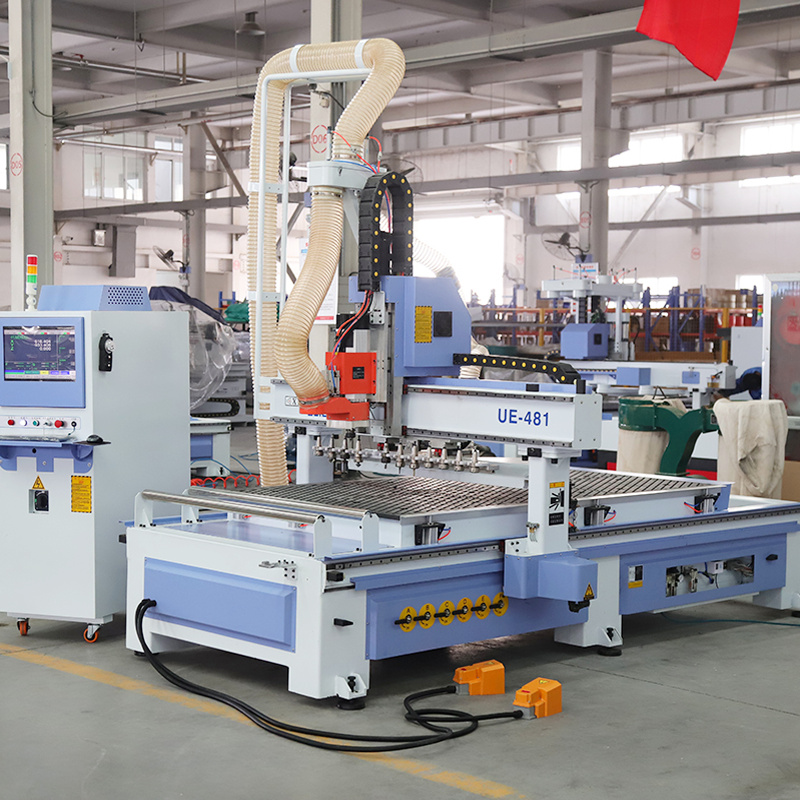
What Matters in the Machine Setup
Machine structure and clearance
Look at the real cutter length, fixture height and cutting load. The advertised working area tells you how far the axes travel; it does not tell you how much usable room is left after clamps, pods and long cutters are added.
Spindle and tool interface
Do not choose the machine from spindle power alone. Look at the actual cutter diameter, cutting depth, holder, tool length and cycle. For ATC work, make sure the planned cutters and holders fit the magazine and still leave enough Z clearance.
Table and locating method
A vacuum table works well for broad, reasonably flat blanks. Narrow or variable parts often need locating stops, pins, fixture plates, clamps or pods as well.
Dust extraction
Chips and fine wood dust can affect seating, finish and the work area. Make sure extraction reaches the cutter and that fixtures and locating surfaces can be cleaned easily between parts.
CAM and operator workflow
The controller and CAM software need to support the axes, tool changes, fixtures and the postprocessor—the CAM output that matches your CNC controller. A capable machine can still waste a lot of time if every changeover needs manual work.
Make Sure the Part Still Holds Near the End of the Cut
Do not judge the fixture only when the blank first goes on the table. The weakest moment often comes after pockets and profiles remove most of the material that was helping to hold the part.
| Part condition | Holding method to consider | What to check |
|---|---|---|
| Large and flat blank | Vacuum table | Leaks, spoilboard condition, remaining contact area and cut-through order |
| Narrow rails or small parts | Fixture, clamps, tabs or combined holding | Clamp clearance, repeat location and release method |
| Warped or irregular blank | Mechanical restraint plus a prepared datum surface | Whether the part seats properly and moves when stock is removed |
| Part needing edge or underside access | Pods, elevated fixture or second setup | Support points, cutter access and reference transfer |
| Rotational part | Rotary chuck and support | Centerline, support length, balance and cutter reach |
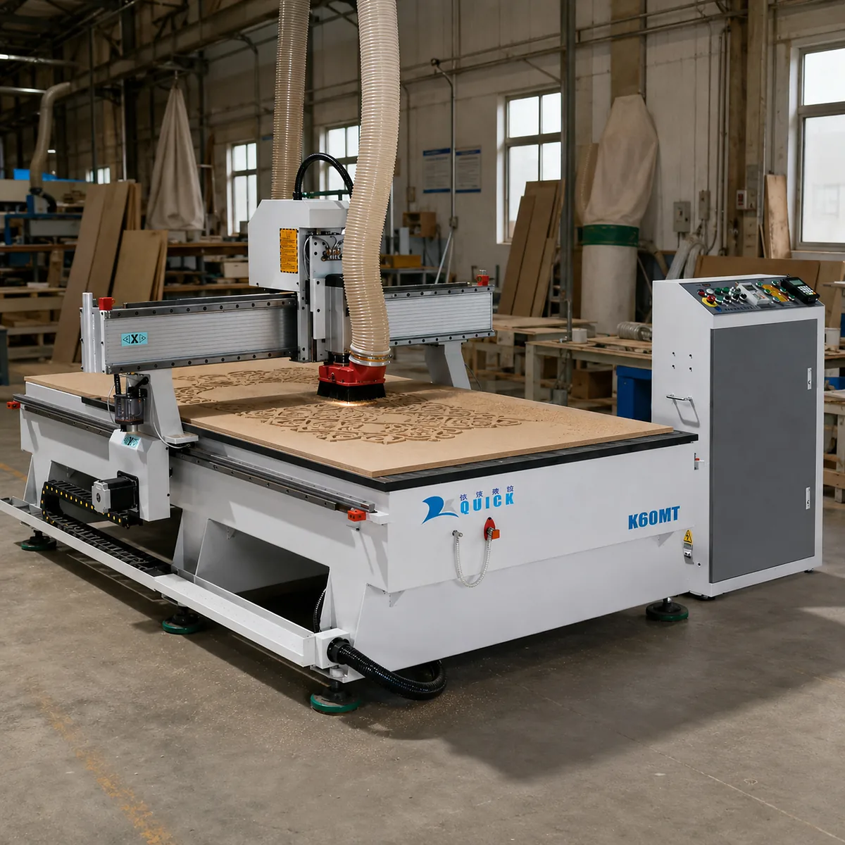
Choose the Cutter for the Edge You Need to Keep Clean
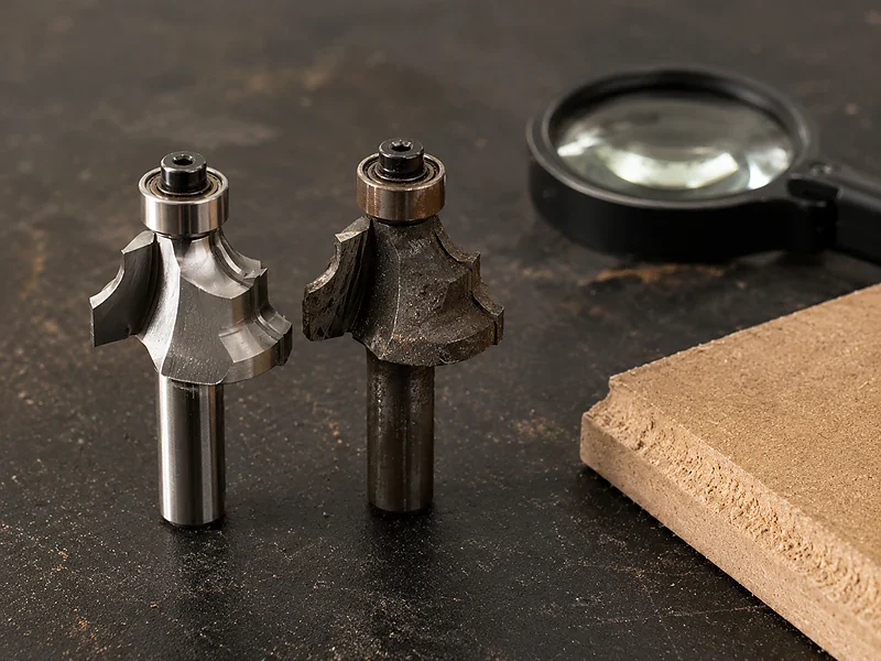
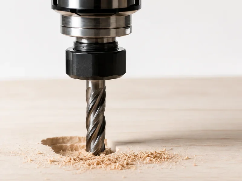
There is no one “best” bit for all solid wood. Start with the operation, grain direction, visible face, depth and chip removal. Roughing and final finishing often need different tools or at least different cutting conditions.
| Job | Tool direction | What to check |
|---|---|---|
| Heavy stock removal | Suitable roughing or spiral cutter | Good chip removal, stable holding and enough material left for finishing |
| Visible top edge | Downward-cutting action can help support the top fibers | Bottom-edge quality and chip removal still need checking |
| Visible bottom edge | Upward-cutting action can help chip removal | Watch for lifting or damage on the top edge |
| Through-cut where both faces need a clean edge | Compression geometry can be tested | Check the actual wood species, grain direction, material thickness and flute transition before treating compression as the answer |
| 3D surface finishing | Ball-nose or another suitable finishing cutter | Tool reach, grain direction, scallop height and finishing time |
| Joinery or decorative edges | Purpose-selected straight, dovetail, V or form tool | Holder compatibility, diameter clearance and safe cutting load |
For more detail, see the CNC router bit guide.
Use chip load as a starting point, not a fixed answer
Tool manufacturers normally connect feed, RPM and flute count through chip load. That relationship is useful, but the final setting still needs to match the wood species, cutter, cutting depth, holding and finish you need.
If the feed is too low for the RPM, the tool can rub and burn the wood. If the cut is too aggressive, the cutter can overload or move the part. Start with the cutter manufacturer’s data, test the actual job and save the combination that works.
See the related CNC feed rate guide for more detail.
Cut in the Right Order
A stable solid-wood job normally works better when blank preparation, roughing and finishing are treated as separate steps.
Record the wood, blank size, visible faces, acceptable defects and which surface will be used as the reference.
Decide where the part locates and make sure it will still be supported after pockets and profiles are cut.
Remove the bulk of the material while leaving a controlled amount for the finishing pass.
Heavy or uneven stock removal can release stress. Some parts need to be re-seated before final sizing.
Choose the cutter, direction and entry based on the surface that will actually be seen and measured.
Keep the measurement timing, edge-quality check and fit check consistent.
These CAM choices are worth testing on the real part
- Lead-in and lead-out near visible grain edges
- Climb vs conventional direction on reversing grain
- Depth per pass in deeper pockets
- Finishing allowance
- Corner motion that may leave burn marks
- Tabs or onion skin on small parts
- Tool reach on 3D surfaces
Fix the Cutting Problem Before Blaming the Machine
| What you see | What may be causing it | What to try first |
|---|---|---|
| Tear-out / chipped fibers | Reversing grain, cutter direction, unsupported edge or too much material in the final pass | Change the entry or direction, leave finishing stock and use a cutter suited to the visible edge |
| Burn marks | Dull tool, rubbing, dwell, trapped chips or too much engagement | Check the cutter, feed/RPM relationship and toolpath before asking for more spindle power |
| Fuzzy edge | Fiber pull, poor cutter choice or weak finishing strategy | Use a separate finishing pass and test the direction on the real grain |
| Chatter / waves | Long tool, weak fixture, too much engagement or machine/fixture movement | Shorten the tool, improve support and reduce unstable load first |
| Part moves near the end | Vacuum area disappears or a small part is released too early | Change the cut order, use tabs/onion skin or improve the fixture |
| Size changes after machining | Moisture change, released internal stress or inconsistent blanks | Control the material condition and keep inspection timing consistent |
A Common Mistake: Choosing the Machine by Table Size
Imagine a furniture shop comparing machines mainly by working area. The chair-side part fits easily on the table, so a basic manual-tool-change router looks good on paper.
- What happens
- The real part needs rough profiling, drilling, finishing and an edge-forming cutter. The operator keeps stopping for tool changes, while the narrow blank becomes harder to hold near the final profile.
- Why it happens
- The machine was chosen from the largest blank size, but nobody mapped the tool sequence or the weakest point in the holding setup.
- What to change
- Build a repeatable fixture, check the lowest remaining holding area and use ATC if the same multi-tool sequence runs every cycle.
- The lesson
- Table size only tells you whether the part physically fits. Tool access, tool changes and holding tell you whether the process actually works.
A Real Production Part Tells You More Than an Easy Demo
If your real job is a long chair rail, a knot-variable door part or an irregular hardwood component, there is not much value in testing only a small, straight-grained offcut. The useful test is the part that is actually difficult in your production.
- Use the same wood species and a representative blank.
- Include the area that is hardest for the cutter to reach.
- Include the smallest holding area near the end of the cut.
- Include the visible grain edge most likely to tear.
- Mark the dimensions and surfaces that really matter on the finished part.
- Keep a record of the cutter, fixture and toolpath that produced the result.
Which Machine Fits Your Solid-Wood Parts?
Do not start from a model number. Start from the part, the number of machining faces, the tool list and the way the blank will be held.
Questions We Often Hear About CNC Routing Solid Wood
Can a CNC router cut solid wood?
Yes. A production CNC router can profile, pocket, drill and carve solid wood when the machine, cutter, holding and toolpath match the part. Solid wood needs more process control than MDF or other uniform sheet materials because grain, knots, moisture and blank variation change the result.
What type of CNC router is best for solid wood furniture parts?
Start with a 3-axis router for mainly flat-face work. Choose ATC when the normal part uses several cutters. Add rotary or 5-axis capability only when the geometry really requires machining around the part or from several directions.
Do I need an ATC CNC router for solid wood?
ATC makes sense when the same part repeatedly needs roughing, finishing, drilling, profiling or edge-forming tools. If most jobs use one cutter and manual changes are not slowing the work down, a standard router can still be the better choice.
Is vacuum hold-down enough for solid wood?
It can be enough for broad, reasonably flat blanks. Narrow, warped or porous parts often need stops, clamps, pods, fixtures or a combination. Check the holding at the weakest point near the end of the cut.
How does moisture affect CNC-machined solid wood?
Wood can change size as its moisture changes, and movement differs by grain direction. Keep the incoming wood condition under control and measure important dimensions under consistent conditions.
Which router bit should I use for hardwood?
Choose the cutter from the operation, visible edge, grain direction, depth and chip-removal needs. Upcut, downcut, compression, roughing, finishing and form tools solve different problems. Start with the cutter manufacturer’s data and then test the real job.
How do I prevent burning when routing solid wood?
Keep the cutter sharp, avoid dwell, remove chips and use a feed/RPM combination that cuts instead of rubs. Burn marks can also come from too much engagement or slow motion in corners.
How do I reduce tear-out along the grain?
Test the cutter direction on the real grain, place lead-ins away from sensitive edges and leave material for a light finishing pass. One heavy pass should not be expected to create the final visible surface.
When is a 5-axis CNC router worth it for solid wood?
Choose 5-axis when the part really needs multi-face access, compound angles or complex curved machining that would otherwise require too much repositioning. More axes do not fix poor blanks, weak fixtures or bad CAM.
References
- USDA Forest Products Laboratory — Wood Handbook: Moisture Relations and Physical Properties of Wood
- Amana Tool — Solid-Wood Spiral Router Bit Feed and Chip-Load Reference
- NIOSH — Wood Dust From Automated Routers
These references support the process principles above. For a specific machine, match the final setup to the actual wood, part, fixture and production requirement.
Want to Know Which Setup Fits Your Part?
Send us the wood species or material, one drawing or part photo, blank size, the machining faces or operations you need, and your output target. That is enough for a first discussion. We can then narrow down whether a 3-axis, ATC, rotary or 5-axis setup actually makes sense.
If you already have a cutter list, fixture drawing or CAM information, send that too—but you do not need it for the first message.
Send Us Your Solid-Wood Part
Frannie
Hello, I’m Frannie, a CNC machinery specialist with 15 years of experience in the woodworking CNC industry. I help furniture factories, cabinet makers, woodworking workshops, and production businesses choose CNC machines that match their production needs, factory size, budget, and efficiency goals.
My work focuses on solving real production problems, including replacing outdated equipment, improving machining efficiency, reducing labor costs, and upgrading to smarter CNC solutions. I also support customers with machine installation guidance, operation training, video support, and on-site training when needed, helping them use their machines more confidently and effectively.